low pass filter resistor/capacitor values?

hey guys,

I think I'm getting some noise from my circuit in the signal from my DAC to my piezo speaker. I'm updating the DAC around 30,000 times a second, and when I move my servos to different extensions, which changes the speed of my animating lights as well, what was a high pitched sound with a slight buzzing turns into a lot of buzing. If I extend them more it goes back to semi-normal, then back to heavy buzzing again.

So I thought it might be prudent to add a low pass filter and see if that helped. I'd left it out of my circuit so I could see if I needed one in the first place.

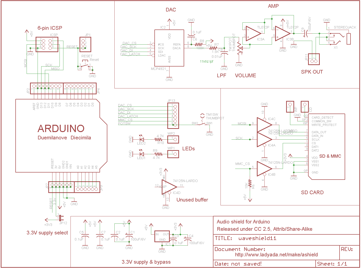
Anyway, I was looking at the audio sheild schematic to see how LadyAda implemented one, and hers states that it is an 11khz LPF, and uses a .1uf capacitor and a 1.5K resistor.

Since my circuit I would like to be able to produce frequencies up to 15,000 hz, I decided to find a calculator on the web to tell me how big a resisotr I needed to make my low pas filter filter out frequencies higher than that instead.

This is the calculator I found:
http://sim.okawa-denshi.jp/en/CRtool.php

Well, to make a long story short, when I put in my desired frequency, it tells me I need a .1uf capacitor and a 110ohm resistor. I thought it odd that it was so low compared to what was used in the Audio Shield, so I tried putting in 11khz instead. This brought the value up to only 150ohms.

So what gives? Is this calculator wrong, or is the wrong size resistor listed in the Audio Shield schematic?

I think it depends on whether you want the filter to pass at a certain frequency or have good attenuation at a certain frequency.

The "corner" frequency of a simple RC filter is 1/(2piR*C). So with 1.5k and 0.1uF the corner frequency is about 1kHz, which means that the signal is reasonably well attenuated (about 20dB) at 11kHz.

With 150ohms and 0.1uF the corner frequency is about 11kHz which means that frequencies from 0 to about 11kHz pass through.

But I don't think any of this is your problem :slight_smile: The "right" answer to noise is not to filter it out but to not let it get in. Your wiring might have more to do with this noise than anything else. Try to keep your servo wires clear far apart from the audio.

--
The Gadget Shield: accelerometer, RGB LED, IR transmit/receive, light sensor, potentiometers, pushbuttons

Well, I tried the calcualtor suggested 100ohm and .1uf capacitor. I can hear it working when I pull the capacitor off and pop it back on, though it doesn't seem to have a huge effect. It certainly doesn't do anything to get rid of the buzzing. A larger resistor would supposedly filter everything over 1000hz, but I don't think I want that.

I guess I'm gonna look over my code some and see if I can spot anything that might cause the issue.

Rugged:
Ah, I see now. Thanks. I'll try using the 1.5K then. I'm not very confident it will get rid of the buzzing since that is a lower sound but it could be high frequencies causing weird harmonics in the piezo for all I know, so maybe it will help.

Okay, the LPF with a 1.5K resistor gets rid of a ton of the noise. But it also makes the piezo really quiet even when outputting a 4,000hz tone.

And it's still like half the normal volume with a 620ohm.

I stuck a 330 on there, and it's a little louder but the pulsing noise is becoming more apparent too.

Guess the problem is elsewhere. But I think I'll include space on my boards for a LPF, just in case.

So what gives? Is this calculator wrong, or is the wrong size resistor listed in the Audio Shield schematic?

In fact, the adafruit Wave Shield schematic shows 1.5K Ohms and 0.01uF (not 0.1 uF)

The 3dB cutoff frequency (assuming zero ohm source impedance and infinite impedance load) is given by 1/(2 * Pi * R * C) which is approximately 10.6 kHz.

With the web calculator, if you let fc = 11kHz and C = 0.01 uF, it tells us that R = 1.5K

No discrepancy.

For your filter and the web calculator, when you told it to use a 0.1 uF capacitor, it gave you 110 Ohm resistor. Try it again with a 0.01 uF capacitor. You get 1.1K Ohms, right? With 0.001 uF capacitor you get 11K Ohms. Etc.

You don't want the impedance of the filter to be lower than a few hundred Ohms, otherwise the ATmega output pin will be overloaded

Note that the load for the low-pass filter on the WaveShield is a high impedance amplifier and a potentiometer that gives a load impedance a lot higher than the low-pass filter. If you connect a lower impedance load, the LPF characteristics will change. (lower output voiltage, higher cutoff frequency).

Of course, as you mentioned it remains to be seen whether a low-pass filter gets rid of the buzzing, since, to me, buzzing indicates a lower frequency impressed on the audio rather than a higher frequency. I mean there are buzzes (high-frequency whiney sounes) and there are buzzes (low-frequency raspy sounds).

I general, effective bypassing of any analog components and careful attention to things like ground loops, which can effectively pick up and amplify digital (and other kinds of) noise, is the starting point for signal integrity analysis.

On the other hand, since the piezo element is non linear as are our ears, it may be that experimenting takes less time than more careful analysis. See Footnote.

Regards,

Dave

Footnote:
"In theory, there is no difference between theory and practice.
In practice, there is."
---Attributed to various scientists and other celebrities

Whoops!

I dunno how I read that as 0.1uf, I must have looked at it three or four times.

So if lowering the value of the capacitor raises the frequency, then that would explain why putting the correct 0.01uf capacitor on there just now while I still had the 330ohm resistor I was most recently testing with seemed like it did nothing. Probably was filtering too high a frequency.

As for burning out the Arduino pins, I thought of that already. I didn't simply connect a tiny resistor between the DAC and the piezo speaker, with a capacitor going to ground in the middle. I also attached a larger resistor in series with the piezo to make sure it wouldn't draw enough current. That is, when I tested with those smaller resistors. I didn't think I needed one with the 1.5K on there.

I'm not too knowledgeable about stuff dealing with impedance or how that might affect the voltage in my circuit, so I'll just take your word for it that that will affect the output. None of the things I attempted though really seemed like they were fixing the underlying problem though, just hiding it.

I think perhaps my DAC's voltage supply is noisy, or the servos are introducing noise or something. I wish I had an oscilliscope so I could see what's going on. I guess I will try adding another bbypass capacitor here and there.

Changing the code that sets the chip select pin for the dac high to some faster access code I'd written seemed to help somewhat. Perhaps I will try lowering the update speed and see how that goes, though I don't think that will help. Updating at 30khz was actually much better sounding than when I was generating the 4000hz tone by updating 8000 times a second. Of course I was generating a 15khz tone with the 30lhz test. I don't yet have code in to generate specific tones regardless of update speed.

Keep in mind that an RC filter is NOT a brick wall filter. If you look at a plot of it, there will be a gentle slope off of the frequency.

Just did a quick check...

About 2/3 down the page they show the "step-response" graphs.

I'll reiterate what others have mentioned and add a little more.

  • Since RC filters have a gentle slope... higher sampling rates will shift their DAC noise up in frequency and make the RC filters more effective. This is often called "oversampling" in the CD/DAC audio world. This won't help with RF noise, though.

  • Motors are extremely noisy devices in the RF realm. The closer they are to an amp/signal wire, the more electrical noise there will be on the output. Shielding the motor will help a little but is usually more trouble than it's worth.

  • Grounding and ground loops can be a royal PITA to clean up and fix. The simplest way is to use a star ground for everything, but this isn't always practical. If you're using a ground bus, put the high current and noisy stuff closest to the PSU ground. Digital stuff is just after that. Analog output is usually furthest away. Remember V=IR? Ground returns have a tiny resistance and high current pulses will show up as a voltage somewhere. If that somewhere is a sensitive amp, it will translate as noise into the output device.

  • As a side warning, just about any side by side combination of resistor and capacitor will try to form some kind of pass filter. If you try stacking these, you will end up with a complex filter. I think this point is mostly irrelevant with an AVR+piezo, but it's worth mentioning for the archive.

  • You can try adding PSU filter capacitors at strategic places, but make sure they are grounded properly (star ground preferred). See my grounding paragraph above.

  • You can try adding filter inductors at strategic places, but do not use them in series with high current devices. I generally don't like inductors because they can become a short range antenna for the noise.

Just about everything on this list comes from what I've learned lurking on the audio forums. Didn't think I'd be using that knowledge here. :slight_smile: There are more complicated setups and explanations, but I think some combination of the above will help you. It's late and my eyes are crossing, but I think I hit on the major points of your problem. Good luck.

I just figured out now where a ton of noise in my circuit was coming from...

I'd connected pins on my shift register which needed to be held high and low directly to VCC and GND.

I don't know why it didn't fry the shift register in all the last few months I've had it hooked up that way, but as soon as I connected them via 10K resistors, most of the noise went away. Also my servos seem to have stopped twitching quite so much.

I wonder if this also will result in better battery life?

I kinda doubt that, cause if the shift register really was drawing that much juice it would surely have released the magic smoke. So I think my goof was probably just making it really easy for noise from the shift register to get into the rest of the circuit rathe than sucking down tons of current.

[edit]

And I just tested updating the dac 8000 times a second instead of 30,000 times a second. I still get some pulsing there probably from the servo interrupt interfering with the update speed, but there's a lot less noise there as well.