LowPower.h doesn't work

Hi,
I have an Atmega328p on the breadboard, and it runs with a crystal at 8mhz.
I have the multimeter in serial and i can clearly see the mA.
The problem is that when I use one of these two commands they doesn't make any differce to the mA consuption:

LowPower.idle(SLEEP_8S, ADC_OFF, TIMER2_OFF, TIMER1_OFF, TIMER0_OFF,SPI_OFF, USART0_OFF, TWI_OFF);

or

LowPower.powerDown(SLEEP_8S, ADC_OFF, BOD_OFF);

the consuption is the same if i use a delay(8000);

Please post the complete sketch, using code tags, and a circuit diagram.

Excellent tutorial here: https://www.gammon.com.au/power

Im watching your link, is really interesting!
and now i have used this void loop():

void loop() {
  set_sleep_mode (SLEEP_MODE_PWR_DOWN);  
  sleep_enable();
  sleep_cpu ();  
}

now the mA drops from 15.9mA to 12.1mA, a great start!

Keep reading Nick Gammon. keep looking for what is drawing so much current

and come brag when it's 12.1 uA!

a7

For the bare bones setup that Nick Gammon describes, this should be about 0.36 mA. So where is 11.7 mA going? Post a circuit diagram!

Yeah, i maybe know where they went :slight_smile:
in reality my project is this:

Tomorrow i will unsolder the led of the module that convert 5v to 3.3v .
Btw with this code:

#include <avr/sleep.h>
#include <avr/wdt.h>

const byte LED = 9;

void flash ()
  {
  pinMode (LED, OUTPUT);
  for (byte i = 0; i < 10; i++)
    {
    digitalWrite (LED, HIGH);
    delay (50);
    digitalWrite (LED, LOW);
    delay (50);
    }
    
  pinMode (LED, INPUT);
    
  }  // end of flash
  
// watchdog interrupt
ISR (WDT_vect) 
{
   wdt_disable();  // disable watchdog
}  // end of WDT_vect

void setup() {
  delay(15000); //delay time in case to upload
}

void loop() {
  //delay(3000);
  flash ();
  
  // disable ADC
  ADCSRA = 0;  

  // clear various "reset" flags
  MCUSR = 0;     
  // allow changes, disable reset
  WDTCSR = bit (WDCE) | bit (WDE);
  // set interrupt mode and an interval 
  WDTCSR = bit (WDIE) | bit (WDP3) | bit (WDP0);    // set WDIE, and 8 seconds delay
  wdt_reset();  // pat the dog
  
  set_sleep_mode (SLEEP_MODE_PWR_DOWN);  
  noInterrupts ();           // timed sequence follows
  sleep_enable();
 
  // turn off brown-out enable in software
  MCUCR = bit (BODS) | bit (BODSE);
  MCUCR = bit (BODS); 
  interrupts ();             // guarantees next instruction executed
  sleep_cpu ();  
  
  // cancel sleep as a precaution
  sleep_disable();
}

thats from the link, now the minimum is 11.9 mA, maybe unsoldering the led always on from the converter i will get 8mA, what you think?

I think that LowPower.h works fine.

Your measurements on an unknown circuit are more or less meaningless.

I'm here, i unsoldered the led from the 5v to 3.3v converter and I don't know why now the LowPower.h works, with the LowPower.powerDown(SLEEP_8S, ADC_OFF, BOD_OFF); the consuption drops to 10.65mA with this code:

#include "LowPower.h"

void setup(){
  pinMode(9, OUTPUT);
  delay(15000); //for upload codes
}

void loop(){
  digitalWrite(9, HIGH);
  delay(500);
  digitalWrite(9, LOW);
  delay(2500); //check how many mA is using in idle
  LowPower.powerDown(SLEEP_8S, ADC_OFF, BOD_OFF);
}

Yup. No schematic = no sensible insight into the situation.

Who knows? Crystal ball is at the repair shop so I have to improvise.

May I suggest breadboarding just the microcontroller with a crystal & decoupling caps (around crystal + Vcc) and trying to get just that down to the lowest power consumption possible. Then optimize the other peripherals for low power usage. Currently you have no clue what is consuming power and how much of it.

ok sorry... i will make a circuit of the project.
Now i discovered the in this loop():

void loop(){
  digitalWrite(9, HIGH);
  data.t = bme.readTemperature();
  data.p = bme.readPressure() / 100.0F;
  data.h = bme.readHumidity();
  delay(100);
  digitalWrite(9, LOW);
  myRadio.write(&data, sizeof(data));

  LowPower.powerDown(SLEEP_8S, ADC_OFF, BOD_OFF);
  LowPower.powerDown(SLEEP_8S, ADC_OFF, BOD_OFF);
  LowPower.powerDown(SLEEP_8S, ADC_OFF, BOD_OFF);
}

the other 2 LowPower.powerDown doesn't make effect, there is no sleep. The led turns on every 8 seconds, and not 24 sec.

Maybe it is crashing when it wakes up after the first sleep.
Put something like this in setup() to help see if that is the case:

digitalWrite(9, HIGH);
delay(2000) ;  // your choice
digitalWrite(9, LOW);

Really thanks 6v6gt. With your idea, I was trying as you said, but after I did this:

void loop(){
  LowPower.powerDown(SLEEP_8S, ADC_OFF, BOD_OFF);
  LowPower.powerDown(SLEEP_8S, ADC_OFF, BOD_OFF);
  LowPower.powerDown(SLEEP_8S, ADC_OFF, BOD_OFF);
  
  digitalWrite(9, HIGH);
  data.t = bme.readTemperature();
  data.p = bme.readPressure() / 100.0F;
  data.h = bme.readHumidity();
  delay(100);
  digitalWrite(9, LOW);
  myRadio.write(&data, sizeof(data));
}

I noticed that when the myRadio.write comes, the mA goes up to 14mA for 10 seconds (i think beacuse it is slow to transmit and block the whole code while loading) and after that i could count 24 seconds of deep sleep using 11 mA.

Btw, i was thinking, is there a function that disables all the modules?
For example, when i start the bme280 library, with bme.begin();, is there a way to sleep the component? i was thinking like a module_stop() and module_resume() but not from the library of the bme280, directly from the Atmega328p, like a sleep_cpu() or something like that

Ahh, you have a radio, and a bme280 sensor, and you are wondering where the power is going?

Fascinating!

1 Like

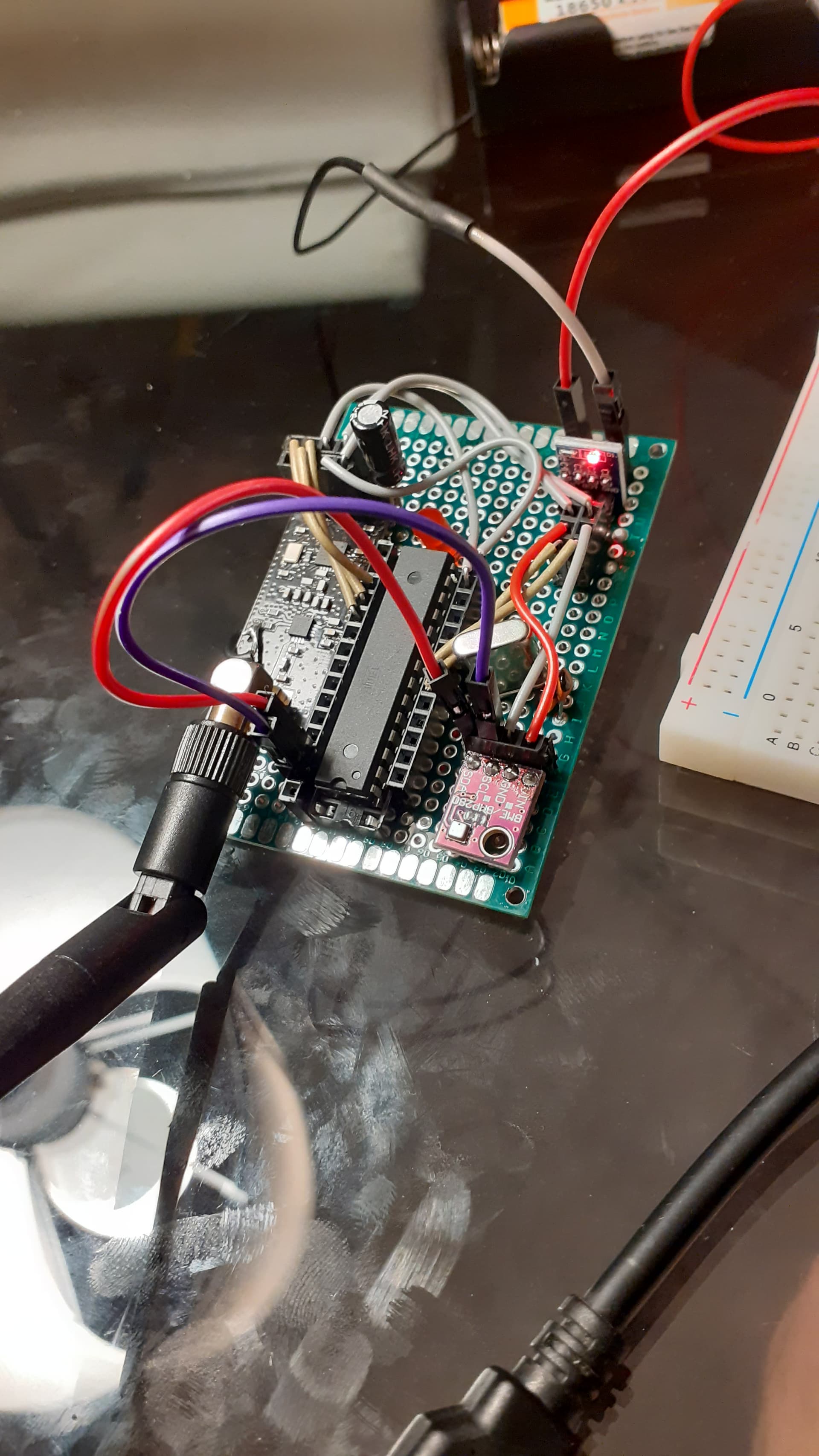
And that is why i sent the image :joy:
Btw i found the commands myRadio.powerDown() and myRadio.powerUp() for the nrf24l01, and I gain 0.2 mA, better than nothing...
obviously I set the transmit power to the minimum:

myRadio.setPALevel(RF24_PA_MIN);

and i'm still searching for the sleep of the bme280... or a command that sleeps all modules

This topic was automatically closed 180 days after the last reply. New replies are no longer allowed.