Major efficiency problems with button matrices

So Im currently working on multiple 4x4 Button Matrices which I want to read as fast as possible/ reasonable. My current Code isn't really working well cause its only able to read the entire Matrix around 5-7 Times a second, only getting slower the more matrices I add.

The below posted Code is the simplified form of the current Sketch Im using, but the part that causes the problem is definitely in it. It reads 4 Button Matrices and stores their Values in a 2D Array called 'MatrixValues'. As said, the code isn't really well made; before I nicely parted everything in reusable functions but that made it even slower.

#include <Adafruit_MCP23X17.h>

Adafruit_MCP23X17 mcp0;
Adafruit_MCP23X17 mcp1;
Adafruit_MCP23X17 mcp2;


//Matrix PCBs
const byte MatrixColumn = 4;
const byte MatrixRow = 4;
const byte MatrixColumnPins[6][MatrixColumn] = { {8, 9, 10, 11}, {0, 1, 2, 3}, {8, 9, 10, 11}, {0, 1, 2, 3}, {8, 9, 10, 11}, {0, 1, 2, 3} };
const byte MatrixRowPins[6][MatrixRow] = { {12, 13, 14, 15}, {4, 5, 6, 7}, {12, 13, 14, 15}, {4, 5, 6, 7}, {12, 13, 14, 15}, {4, 5, 6, 7} };
const byte totalMatrixKeys = MatrixColumn*MatrixRow;

int MatrixValues[6][totalMatrixKeys];
int MatrixValuesOld[6][totalMatrixKeys];


void setup() {
  Serial.begin(115200);
  
  mcp[0].begin_I2C(0x20);
  mcp[1].begin_I2C(0x21);
  mcp[2].begin_I2C(0x22);

//Matrix PCBs
  for (byte i = 0; i < MatrixColumn; i++) {
    mcp[0].pinMode(MatrixColumnPins[0][i], INPUT);
    mcp[1].pinMode(MatrixColumnPins[1][i], INPUT);
    mcp[2].pinMode(MatrixColumnPins[2][i], INPUT);
  }


}

void loop() {
  readExecuter();
  sendExecuter();
  Serial.println("Round"); //used for measuring 'round-trip-time'
}

void readExecuter() {
    int keyNumber = 0;
    // Rows...
        for (byte row = 0; row < 4; row++) {
        mcp[0].pinMode(MatrixRowPins[0][row], OUTPUT); //--> it reads all pin definitions from the global 2D Array MatrixRowPins
        mcp[0].pinMode(MatrixRowPins[1][row], OUTPUT);
        mcp[1].pinMode(MatrixRowPins[2][row], OUTPUT);
        mcp[1].pinMode(MatrixRowPins[3][row], OUTPUT);
        mcp[0].digitalWrite(MatrixRowPins[0][row], LOW);
        mcp[0].digitalWrite(MatrixRowPins[1][row], LOW);
        mcp[1].digitalWrite(MatrixRowPins[2][row], LOW);
        mcp[1].digitalWrite(MatrixRowPins[3][row], LOW);
    
        //Columns...
        for (byte column = 0; column < 4; column++) {
            int keyState0 = mcp[0].digitalRead(MatrixColumnPins[0][column]); //--> it reads all pin definitions from the global 2D Array MatrixColumnPins
            int keyState1 = mcp[0].digitalRead(MatrixColumnPins[1][column]);
            int keyState2 = mcp[1].digitalRead(MatrixColumnPins[2][column]);
            int keyState3 = mcp[1].digitalRead(MatrixColumnPins[3][column]);
            MatrixValues[0][keyNumber] = keyState0;
            MatrixValues[1][keyNumber] = keyState1;
            MatrixValues[2][keyNumber] = keyState2;
            MatrixValues[3][keyNumber] = keyState3;
            keyNumber++;
        }
        mcp[0].pinMode(MatrixRowPins[0][row], INPUT);
        mcp[0].pinMode(MatrixRowPins[1][row], INPUT);
        mcp[1].pinMode(MatrixRowPins[2][row], INPUT);
        mcp[1].pinMode(MatrixRowPins[3][row], INPUT);
    }
}


void sendExecuter() {
    for (int p = 0; p < 4; p++) {
      for (int i = 0; i < 16; i++) {
        if (MatrixValues[p][i] != 1 && MatrixValues[p][i] != MatrixValuesOld[p][i]) {
           Serial.print("Matrix: ");
            Serial.print(p);
            Serial.print(" | ");
            Serial.print("Key: ");
            Serial.println(i);}
          MatrixValuesOld[p][i] = MatrixValues[p][i];}}
  }

Summing the individual Matrices in one big by hardware isn't an option; it has to work with individual ones. I also tried using the pre made librarys for Matrices with the MCP expanders but that did not work at all for me -> literally no output no matter what I've tried,

Help and advice is really appreciated. Thank you!

Why not?

Surely, the hardware neither knows nor cares whether it's being scanned alone, or as part of a bigger picture? :thinking:

So, with 4 keypads, you have still have 4 rows, but 16 columns (or vice-versa)

I really want to keep the system modular therefore the individual 4x4 matrices are there for a reason. Second I don't really think that that would make such a big difference in read-out speed. Sure there would be less pins but even reading two matrices like shown in the code drops the speed significantly.
I think it has to do with some kind of software bug in my program that causes unnecessary delay.

I think it has to do with some kind of software bug in my program that causes unnecessary delay

Ditch the MCP libraries and control the MCPs directly or make a better library. Those things are really simple to control directly and you get a nice small bonus lesson in I2C.

And honestly, seeing how the code revolves about current library I would ditch the entire program and start from scrap. That is likely less labour than to fix this.

Right now you are reading one input per time which is incredibly inefficient as you already noticed. Atleast 6 bytes transactions (if not more) are needed to fetch a single input. You can easily read up to 8 inputs with the same amount of byte transactions. And with an extra byte you can read 16 inputs but I guess this won't be possible with your wiring.

Regards,

Bas

Thank you very much for the input! I do think that it is a problem with the library. I will try to get myself in driving them directly, that sounds like an interesting learning session.

A small pseudo code example

for( int col = 0 ; col < nCol ; col ++ )
{
	Wire.beginTransmission( MCP1_ADDR ) ;
	Wire.write( PORTA ) ;  // assuming columns are on port A
	Wire.write( 1<<col ) ; // set 1 column pin high and the other lows
	Wire.endTransmission() ;

	Wire.beginTransmission( MCP1_ADDR ) ;
	Wire.write( PORTB ) ;  //  select port B. assuming rows are on port B
	Wire.endTransmission() ;

	Wire.requestFrom( MCP1_ADDR, 1 ) ;  // read one byte from Port B
	uint8_t input = Wire.read() ;  // contains data of all 8 inputs on port B

	for( int row = 0 ; row < nRow ; row ++ )
	{
		// process the input to your own array
	}
}

That sound really great and with individual buttons I already have a solid transmission, Very easy indeed! Is there a problem coming when my Rows and Columns are on the same side as in all on Port A?

No not really, you can just use a port for both input and output.

If you have 4 inputs on bit 4 - bit 7 for example you can just shift the input.

uint8_t input = Wire.read() >> 4 ;  // shift bits 4 to the right

For setting the columns (outputs) it also shoudln't matter iirc. And if it does, we can always OR a few bits.

Sorry for asking again but I can't really wrap my head around how I have to implement that. I (think I) understand how I read the entire register of the chip and receive the byte with its values.
But I cant figure out how to set the corresponding IO Directions per Pin and therefore be able to read the Matrix. Would you be able to write a short explanation of that or where I should look to find that out by myself?
Thank you very much!

Check my I2C keypad library - GitHub - RobTillaart/I2CKeyPad: Arduino libray for 4x4 (or smaller) KeyPad connected to an I2C PCF8574

No performance measurements but pretty fast.
Furthermore it can generate an interrupt when keys are pressed, if polling is no option.

No problem.

First an important lesson, RTFD, Read The Fine Datasheet. This can be overwhelming at first, but keep trying to read it, all information is always there. I'll walk you through it.

Inside the datasheet there is this list with al the registers

If you want to write to a register, you need to send 2 bytes over I2C. The first byte tells which register you want to write to, the 2nd byte contains the data you want to put in that register. (this is also explained in the datasheet, but I give a short summary. It is sorta universal)

In code that looks like this. Imagine I want to write 0x0F in register GPIOA (the actual IO)

const int GPIOA = 0x12 ; // see the list

Wire.beginTransmission( 0x21 ) ;
Wire.write( GPIOA  ) ;
Wire.write( 0x0F ) ;
Wire.endTransmission() ;

Also take note. The register is auto-incrementing after a read or write. So if you also would want to write to PORT B (which has address 0x13) you can add a 3rd Wire.write() ; in that code. Theoretically you can fill every register in a single transmission.

Reading from a register works similar. You first need to send 1 byte to tell what register you want to read from and then you perform the read operation.

So if you want to read from GPIOA you do

Wire.beginTransmission( 0x21 ) ;
Wire.write( GPIOA  ) ;  // We select the register, but we dont write to it.
Wire.endTransmission() ;

Wire.requestFrom( 0x21, 1 ) ; // means: I want to read 1 byte
uint8_t input = Wire.read() ;   // fetch byte from buffer

If you would want to read from both PORTA and PORTB at once it would look like this

Wire.beginTransmission( 0x21 ) ;
Wire.write( GPIOA  ) ;
Wire.endTransmission() ;

Wire.requestFrom( 0x21, 2 ) ; // means: Now I wanna read not 1 but 2 whole bytes
uint16_t input = Wire.read() << 8 | Wire.read() ;   // fetch both bytes from buffer and put em in an integer

This is how you read and write from and to registers via I2C.

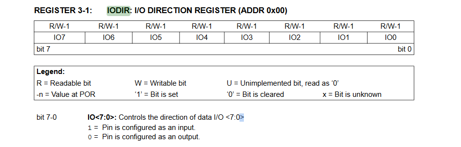
Now back to your question. You need to set the input direction or as you know it 'pinMode'. These are the IODIRA and IODIRB registers on address 0x00 and 0x01 respectively. According to the list.

If you read the list you will see IODIRA and IODIRB. May it be obvious by now where it stands for: IO DIRection. But we do not know if a '1' is an output or input. If you start Ctrl - F'ing through the dataseet on IODIR you will quickly find the anwser.


1 = input
0 = output
(by power up, things are often a '0', so by default both GPIO ports are set as outputs)

Usually when you read in switches you also want to enable to the internal pull-up resistors. But looking at your code I doubt that this is the case here. I'll explain anyways :stuck_out_tongue: . In the register list you can find GPPUA and GPPUB. These are the registers for the pull-ups. If we Ctrl - F in the datasheet at pull-up we will find:
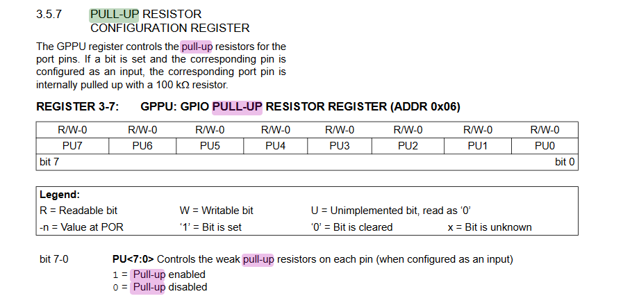
An example. If you want to set the last 4 pins of PORTA AND the last 4 pins of PORTB as inputs with pull-ups enables, you would have to do this:

Wire.beginTransmission( 0x20 ) ;
Wire.write( IORDIRA ) ;  // select register
Wire.write( 0xF0 ) ; // for port A  You can also write 0b11110000 if it makes you happy ;)
Wire.write( 0xF0 ) ; // for port B
Wire.endTransmission()  ;

Wire.beginTransmission( 0x20 ) ;
Wire.write( GPPUA) ;  // select register
Wire.write( 0xF0 ) ; // for port A set internal pull up registers
Wire.write( 0xF0 ) ; // for port B
Wire.endTransmission()  ;

And this my friend is how you 'operate' a datasheet :wink: Ctrl - F!

Hope it helps,

Bas

Thank you so so much! This was literally the best explanation I have ever received. Well structured - straight to the point and with a bit of irony. That's how I like it :slight_smile:
You really made my day. Now I think I know enough to get myself through the world of I/O. And Ctrl-F is indeed the second best feature of a keyboard - only shortly behind Ctrl-Z for when reality hits you.

Have a great day!

---Edit---
Nevermind; found the answer myself. I should not write Low or High to a Pin, even though it is not defined as "Output". That disturbes the data reading.

Would you mind having a quick look over my Code I've written now? I think I understand how everything works but somewhere in it is a little error which makes the Output be only 1 so no Button press is detected.

My rows are connected to 0,1,2,3 and my columns at 4,5,6,7

#include "Wire.h"

uint8_t IO_Mode[4] = {0x7F, 0xBF, 0xDF, 0xEF};
uint8_t IO_State[4] = {0x80, 0x40, 0x20, 0x10};

void setup()
{
    Serial.begin(9600);
    Wire.begin(); // wake up I²C bus

}

void loop()
{
  readExecuter();

}


void readExecuter() {
  for (int i = 0; i < 4; i++) {
    Wire.beginTransmission( 0x20 ) ; //Chip ID 0x20
    Wire.write( 0x01 ) ;  //IODIR Register B
    Wire.write( IO_Mode[i] ) ; //Set corresponding row as output
    Wire.endTransmission();

    Wire.beginTransmission( 0x20 ) ;
    Wire.write( 0x13 ) ; //IO Register B
    Wire.write( IO_State[i] ) ; //Set corresponding row low
    Wire.endTransmission() ;

    Wire.beginTransmission( 0x20 ) ;
    Wire.write( 0x13  ) ;  //read from IO Register B
    Wire.endTransmission() ;

    Wire.requestFrom( 0x20, 1 ) ; 
    uint8_t input = Wire.read(); 

    Serial.println(input, BIN); //dump read to serial
    
    
    Wire.beginTransmission( 0x20 ) ; //set all IO to INPUT
    Wire.write( 0x01 ) ;
    Wire.write( 0xFF ) ; 
    Wire.endTransmission()  ;
    
    }
  }

This was literally the best explanation I have ever received.

Well thank you. It helps that you are a good listener who understands humor :smiley:

At first glanse the repetetive IODIR instructions seem needless. I don't know how you wired things exactly so I may be talking nonsense here.

Often with a matrix your colomns will always be outputs and the rows inputs (or vice versa). You you could set all columns as outputs and rows as input just one time in void setup().

However what you have now, does not hurt. It does make the code perhaps a bit slower with 4 whole byte transactions but that is propably not going to be a bottle neck..

Than I have one side note. The comments are not needed in this line...

Wire.write( 0x01 ) ;  //IODIR Register B

if you create a constant for it. using a constant makes the line self-explanetory, eliminating the need for a comment.

const int IODIR_B = 0x01 ;
...
...
Wire.write( IODIR_B ) ;  // this line is now self explanetory and need no comment anymore.

Also as you are not interested in reading the first 4 bits, you could optionally AND the input with 0x0F like

uint8_t input = Wire.read() & 0x0F;

Have you tested something yet?

Bas

Hi Bas,
Thank you for your kind words :slight_smile:

In my case I think the repeated definitions are needed because the other columns that are not actively used (e.g. LOW) have to be floating; neither high nor low would work.

Constants were the first thing Ive implemented after having a code that works to that extend. Im that guy that does not bother to make a code clean and tidy until its to some extend working.
To AND that byte is a good idea; but I resulted in bit-shifting the 'input' by 4 to the right. Would that be a big difference?

Yes my code is so far working that I can poll every row and get output from it. And at a a really fast pace! Now im working on how to store the output in an Array; so a 16-wide array that can store every keystate (low or high/ pressed or released. Sadly my knowledge of bits and bytes hangs there a bit and I cannot get a working result. Mind giving me a little hint? :wink:

That depends in which bits the result lies. A byte is composed of 8 bits.

bit7, bit6....bit1, bit0
Bit 7 is the Most Significant. So binary 10000000 has a decimal value of 128
Bit 0 is the Least Significant binary 00000001 has a decimal value of 1
They are grouped the same on the IO ports of the MCP. So if PORTB pin 7 is the only HIGH pin, you would read 10000000

A nibble is a group of 4 bits. So a byte has 2 nibbles. There is the upper nibble (bit7-bit4) and the lower nibble (bit3-bit0).

Our heximal notation is particular usefull because ever number/letter corresponds with a nibble. 0x3F => upper nibble has value 3, lower nibble has value 15.

If you have an input like 0b01100000 and you shift it four places to the right
0b01100000 >> 4 = 0b00000110
The result would be 0b00000110 but if you would shift 0b00000110 with 4 (0b.... is binary notation in C code) the result would be 0.
0b00000110 >> 4 = 0

If you AND that same byte with 0xF0 the result is 0b01100000 & 0xF0 = 0b01100000
If you AND that same byte with 0x0F the result is 0b01100000 & 0x0F = 0b00000000

There are often more roads to reach the city of Rome, some are longer than others, some have equal length. Meaning: there are more ways to accomplish your goals. And if often not really matters which method you pick.

If you want to set one bit of a byte without touching the others, you can use OR
0b01100000 | 0b00000001 = 0b01100001
If you want to clear one bit without touchting the others you can use AND again in combination with the ~ (inverts all bits in the byte)
0b01100001 & ~0b00000001 = 0b01100000
if you want to read a single bit of byte and get a boolean result like 0 or 1 than you must shift first and AND afterwards. Here I will read the 5th bit of the byte. I'll do it in 2 lines, but it can be in done 1

0b01100000 >> 5 = 0b00000011
0b00000011 & 0b00000001 = 1
in one line
(0b01100000 >> 5) & 0b00000001 = 1
(also `0b00000001, 0x01, 1, 01 (octal) are all the same)

Arduino `language' ( = C++ Plus many extra functions) has a bucketload of all kind of usefull functions. If you want to write or read a single bit of a byte You can google for bitRead(), bitWrite(), bitClear() and bitSet(). These functions (or macros actually) do the exact same as I just explained but they are more easy to use.

Regards :coffee:

Bas