Making sense of Optical Mouse sensor data [ADNS2620] [Fixed]

I am interested in simulating a mouse pointer (say a square on a Cartesian coordinate system). I would need to convert DELTA_X & DELTA_Y data received from ADNS2610 Optical Mouse Sensor.

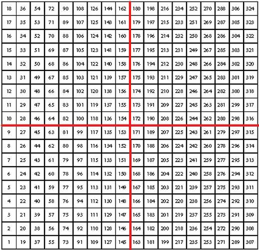
Looking at the datasheet, there is an 18 x 18 matrix of possible pixel read ranges. I divided the matrix into 4 parts, where each part can potentially mean a direction of movement:

I wrote a small app which lights up each pixle when data is receive just to get a visual understanding. And sure enough, parts of each quadrant would light up when the sensor is moved UP, Down, LEFT, or RIGHT.

So a method to get direction would be:

private int getDirectionInt(int val) //where val can be DELTA_X or DELTA_Y
{
   if ((val >= 163 && val<= 171) ||
      (val >= 181 && val<= 189) ||
      (val >= 199 && val<= 207) ||
      (val >= 217 && val<= 225) ||
      (val >= 235 && val<= 243) ||
      (val >= 253 && val<= 261) ||
      (val>= 271 && val<= 279) ||
      (val>= 289 && val<= 297) ||
      (val>= 307 && val<= 315))
      {
          return 4; // Quadrant 4 (Lower Right)
      }
else if ((val>= 1 && val<= 9) ||
     (val>= 19 && val<= 27) ||
     (val>= 37 && val<= 45) ||
     (val>= 55 && val<= 63) ||
     (val>= 73 && val<= 81) ||
     (val>= 91 && val<= 99) ||
     (val>= 109 && val<= 117) ||
     (val>= 127 && val<= 135) ||
     (val>= 145 && val<= 153))
     {
          return 2; // Quadrant 2 (Lower Left) 
     }
else if ((val>= 10 && val<= 18) ||
     (val>= 28 && val<= 36) ||
     (val>= 46 && val<= 54) ||
     (val>= 64 && val<= 72) ||
     (val>= 82 && val<= 90) ||
     (val>= 100 && val<= 108) ||
     (val>= 118 && val<= 126) ||
     (val>= 136 && val<= 144) ||
     (val>= 154 && val<= 162))
     {
           return 1; // Quadrant 1 (Upper Left)
     }
else if ((val>= 172 && val<= 180) ||
     (val>= 190 && val<= 198) ||
     (val>= 208 && val<= 216) ||
     (val>= 226 && val<= 234) ||
     (val>= 244 && val<= 252) ||
     (val>= 262 && val<= 270) ||
     (val>= 280 && val<= 288) ||
     (val>= 298 && val<= 306) ||
     (val>= 316 && val<= 324))
     {
           return 3; // Quadrant 3 (Upper Right)
     }
else
    {
        return 0; //Idle
    }
}

I then have a method which moves the square:

private void moveSquare()
{
int dX = getDirectionInt(DELTA_X);
int dY = getDirectionInt(DELTA_Y);
int ddX, ddY;

int delta=5; // How much to move the square 

if (dX == 4)
    ddX = delta;
else if (dX == 3)
    ddX = delta;
else if (dX == 2)
    ddX = -delta;
else if (dX == 1)
    ddX = -delta;
else
    ddX = 0;

if (dY == 4)
    ddY = -delta;
else if (dY == 3)
    ddY = delta;
else if (dY == 2)
    ddY = -delta;
else if (dY == 1)
    ddY = delta;
else
    ddY = 0;

squareX = squareX + ddX;
squareY = squareX + ddX;

mySquare.refresh(); //Re-draws the square with new center
}

Somehow I think I am walking the wrong path. This approach is not as fluid as I would like, ie. The mouse pointer moves much nicer than my square.

Any thoughts?
LucidGold:
This approach is not as fluid as I would like, ie. The mouse pointer moves much nicer than my square.

Any thoughts?

I'm a bit confused about what you try to do here and where the problem lies.

Are you saying, that on your 18x18 matrix the mouse doesn't behave as nicely as a mouse pointer on a 1680x1050 screen? That's hardly surprising due to the lower resolution. Also, most mouse drivers use exponential behaviour so that small movements are slower than large movements and changes in acceleration behave as if the mouse had inertia. To test it, move your mouse cursor slowly for a stretch and the return it quickly to the originating point. The cursor won't end up in the same place.

Also, how does deltaX and deltaY relate to that matrix? If the matrix shows possible values from the sensor, I would have expected deltaX and deltaY to be both encoded in one reading. (eg Cell 29 means deltaX=-8 and deltaY=+2). Or is the matrix just your display, then what's the use of the function getDirectionInt()?

Perhaps it would help a little, if you also posted the code you use to retrieve the data from the mouse sensor.

Korman

By the way, that decoding can be done in a lot more compact way, if necessary.

Coding used to get values from the sensor is as follows:

#include <adns2620.h>

//Name the ADNS2620, and tell the sketch which pins are used for communication
ADNS2620 mouse(18,19);

//This value will be used to store information from the mouse registers.
unsigned char value=0;

void setup()
{
	//Initialize the ADNS2620
    mouse.begin();
    delay(100);
	//A sync is performed to make sure the ADNS2620 is communicating
    mouse.sync();
	//Put the ADNS2620 into 'always on' mode.
    mouse.write(CONFIGURATION_REG, 0x01);
    
	//Create a serial output.
    Serial.begin(9600);
}

void loop()
{
	//The DELTA_X_REG and DELTA_Y_REG store the x and y movements detected by the sensor

 if (Serial.available() > 0) 
   {
      // read the incoming byte:
      int incomingByte = Serial.read();

      if (incomingByte == 'a')
      {
	//Read the DELTA_X_REG register and store the result in 'value'
        value = mouse.read(DELTA_X_REG);
    	//Print 'value' to the serial port.
        Serial.print(value, DEC);
        Serial.print(',');
        
    	//Read the DELTA_Y_REG register and store the result in 'value'
        value = mouse.read(DELTA_Y_REG);
    	//Print 'value' to the serial port.
        Serial.println(value, DEC);
      }
   }
}

Are you saying, that on your 18x18 matrix the mouse doesn't behave as nicely as a mouse pointer on a 1680x1050 screen? That's hardly surprising due to the lower resolution.

I meant to say that my current square movements on the Cartesian graph are not as smooth as a mouse pointer. i.e. my code still needs work, which why I am posting here.

Also, most mouse drivers use exponential behaviour so that small movements are slower than large movements and changes in acceleration behave as if the mouse had inertia. To test it, move your mouse cursor slowly for a stretch and the return it quickly to the originating point. The cursor won't end up in the same place.

I am aware of that.

Also, how does deltaX and deltaY relate to that matrix? If the matrix shows possible values from the sensor, I would have expected deltaX and deltaY to be both encoded in one reading. (eg Cell 29 means deltaX=-8 and deltaY=+2). Or is the matrix just your display, then what's the use of the function getDirectionInt()?

Sorry I wasn't very clear. The matrix represents min and max X & Y DELTA values. I made an assumption that I can relate the sensor movement direction to the matrix values.

Let me summarize:

Given: Center of Square say (Sx,Sy)
Given: DELTA_X & DELTA_& of Optical Mouse Sensor

I need to convert DELTA_X & DELTA_Y into something like an increment where it can be used:
New center of square = (Sx+New_Delta_X, Sy+New_Delta_Y)

Sorry for the confusion.

Any thoughts or suggestions please :slight_smile:

My issue is with understanding the DELTA_X and DELTA_Y. I have no problems in plotting, graphing or hardware design.

The work of the ADNS2620 as defined by the datasheet:

"It is based on optical navigation technology, which measures changes in position by optically acquiring sequential surface images (frames) and mathematically determining the direction and magnitude of movement."

"The output format is a two wire serial port. The current X and Y information are available in registers accessed via the serial port."

"Register Address Notes
------------------------------------------
Delta_Y 0x42 Y Movement
Delta_X 0x43 X Movement"

"Delta_Y USAGE: Y movement is counted since last report. Absolute value is determined by resolution."
"Delta_X USAGE: X movement is counted since last report. Absolute value is determined by resolution."

The the datasheet provides a table/matrix which is described as:
"Pixel Map (sensor is facing down, looking through the sensor at the surface)"

Here is a picture of it, I modified the image by adding two red lines to divide the matrix into quadrants (to better understand the numbers).
Imgur

Other optical mouse sensors provide negative and positive values. The ADNS2620 provides positive values ranging from [1-324] for each X & Y delta.

Where did I go from here? Well, with my assumption of "Quadrants", I am able to get a sense of the movement direction by checking "Quadrant" range values through my getDirectionInt method/function. I then create my own "movement delta" which is a static value of how much should my simulated mouse pointer (Square) move on a Cartesian coordinate system.

Currently my simulated pointer (Square) is not moving very fluidly, and that is due to my constant movement delta, which has no association with the actual speed of mouse movement. I am trying to figure that out.

I hope this is a little more clear than my first attempt.

Am I going about this the right way?

Hello,

I think you're mixing up two things which aren't related. The matrix with 324 cells you posted is just a picture the sensor took. If you want to use the sensor as a mouse, I think it has no relevancy and you can ignore it and you just need delta_X, delta_Y and the elapsed time since you last read those registers.

Whenever you read those registers, they tell you how many units - whatever those are - the mouse has moved in that direction since you last read the same register. Values go from -128 to +127. If you read those values with more or less constant frequency, you wouldn't have to worry too much about the time difference as it's constant. If it varies widely, you need to take it into account. Depending on the reading frequency, the values delta_X and delta_Y vary. In the most simple case, the code is something like:

int pos_X = 0;
int pos_Y = 0;
...
void loop() {
   int_8t delta_X = mouse.read(DELTA_X_REG);
   int_8t delta_Y = mouse.read(DELTA_Y_REG);

   // This part here would more complicated if you want to have ballistic behaviour of the mouse
   pos_X += delta_X;
   pos_Y += delta_Y;

   // Magic function to display the cursor on your preferred device.
   display_my_cursor (pos_X, pos_Y);

   // Give the mouse some time to move so we get larger values for delta_X and delta_Y
   // In reality you probably won't use delay() 
   delay (50);
}

These values then need to be properly scaled and then applied to your current origin. With the scaling you can be creative. But forget about that 324 cell matrix.

Perhaps that helped a little.

I would love to ignore the matrix of 324 cells. However, the values that represent DELTA_X_REG and DELTA_Y_REG range from 1 to 324. I never receive data in the range -128 to +127. I have seen other optical mouse sensors that do, including the PAN3101.

There must be some scaling related to the 1 to 324 range, unless I am still missing the big picture :~

I corrected my code above to read in signed bytes. then you have -128 to 127.

Korman

Korman, thank you for the clarification. I am still unable to obtain range values from +127 to -182, even if I declare delta values as uint_8t. I am currently sending delta values upon request to not overload my "mouse". I prefer to do the processing at the receiving end (C# application). I am not interested in emulating the mouse at the OS level; moving a square would be more than enough.

When I send values over the wire, they are converted to DEC which bring back 1 to 324 range.

If I can scale the values to [+127 -128] this would at least fix the Square x & y increments. I then will need to figure out the speed, which should be doable.

All I would like to do is move a Square drawn on a picture box (C# application) by moving my "mouse". I easily control the drawing functionality of the Square. However, I am stuck at decoding the mouse delta values to help me.


I believe all I need are two things:
[1] Correct direction of mouse movement: which can be +x or -x & +y or -y. With this I can know if I should SUBTRACT or ADD. So the SIGN of the delta is important
a. SIGN of X movement - or +
b. SIGN of Y movement - or +

[2] Speed of mouse movement, which can be obtained by time just as you noted.

Once I have [1] & [2] I then apply them to the current Square center (which I always have).

This way I have a new Square center:
(Current_Square_Center_X [1a] [2] , Current_Square_Center_Y [1b] [2] )

I then plot my new Square center.

Does this make any sense?

Not uint8_t, that's unsigned and a range from 0 to 255. int8_t is the signed version which goes from -128 to 127.

I hope that clears it up.

Korman

Korman, it all makes sense now.

I initially used int_8t, which resulted in compile errors. I tried to look it up but no luck. I then used uint8_t because it compiled (you pointed out I shouldn't).

However, int8_t did the trick. With all my decoding at the application level (C#), I am still missing a couple of tweaks; but I can handle them.

Final arduino code:

#include <adns2620.h>
ADNS2620 mouse(18,19);

void setup()
{
    mouse.begin();
    delay(100);	
    mouse.sync();
    mouse.write(CONFIGURATION_REG, 0x01);
    Serial.begin(9600);
}

void loop()
{
 if (Serial.available() > 0) 
   {
      int incomingByte = Serial.read();

      if (incomingByte == 'a')
      {       
        int8_t delta_X = mouse.read(DELTA_X_REG);
        int8_t delta_Y = mouse.read(DELTA_Y_REG);
        
        Serial.print(delta_X, DEC);
        Serial.print(',');
        Serial.println(delta_Y,DEC);
      }     
   }
}

Thanks for your help Korman!

Glad it helped.

Korman