I am building 6 LED modules which are controlled by 74hc595 shift registers that are daisy chained. One shift register on each module. The modules are in a straight line. I want to power the whole project with a 12v external battery. Since I am driving LEDs it has been recommended to me to use the TPIC6A595s for their current rating.
To avoid frying anything, is this the best way to do this? I want to individually control each LED but i want them to be powered by the external power source and not getting regulated down to 5v by the arduino. My current wiring schematics is exactly like the tutorials for ShiftOut. I feel like I should have transistors somewhere?
I feel like it cant be as simple as just swapping in the TPICs and having more current through because itd still be going through the ardunio first correct? I just want the arduino to signal.
I already have all my code required to run it on the basic 595s, I just am hardware clueless.
The TPIC6x595 provide the transistors. These are basically 74HC595 with open-drain outputs added, designed to sink current from high voltage sources.
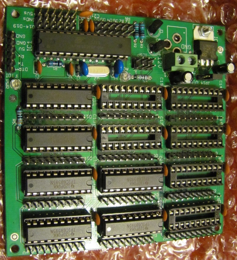
For example, I offer this board which uses TPIC6B595 to sink current thru LED strips powered from 12V. Each LED needs a current limiting resistor, of value (Vsource - VFled)/current = Resistor ohms. So for 12V, single Red LED with Vf of 2.2V, and 20mA (0.02A), R = 490 ohm.
Make sure you have 0.1uF cap on VCC pin of each shift register, and NOT on any signal lines. http://www.crossroadsfencing.com/BobuinoRev17/
The TPIC6x595 provide the transistors. These are basically 74HC595 with open-drain outputs added, designed to sink current from high voltage sources.
For example, I offer this board which uses TPIC6B595 to sink current thru LED strips powered from 12V. Each LED needs a current limiting resistor, of value (Vsource - VFled)/current = Resistor ohms. So for 12V, single Red LED with Vf of 2.2V, and 20mA (0.02A), R = 490 ohm.
Make sure you have 0.1uF cap on VCC pin of each shift register, and NOT on any signal lines. Cross Roads Electronics
SO how do i provide the TPICs power with out making all that current go through arduino... by the end of this their could be some good amounts of current flowing and i dont want to fire anything... I'm hoping to eventually make my project mass produced
The application Im going to be using these in will require a 12v power supply so thats out.
I guess Im having a hard time grasping the whole shift register thing. When using transistors my understanding is the arduino just controls it like a switch, switching on the high current. But with the shift registers, the current for the LEDs is flowing through what I thought would be only signal wires.
Thats what I want to do here, but i need the LEDs to be individually addressable.
I have disconnected my board from the USB and attached a 9v battery to the circuit with one of the + leads going to Vin on the board. however when the push button cycles to off, one of the 5 modules stays brightly lit. This makes me scratch my head. All the others go out
If you use a TPIC6B595 you can connect the cathode of the LED to the output pin. The anode to a resistor and the other end of the resistor directly to 12V.
The resistor will have to be calculated for 12V and not the usual 5V.
The chip still takes its power from the 5V line on the arduino but the LED current is taken from the 12V supply.
My current wiring schematics is exactly like the tutorials for ShiftOut.
I hope not, if so move those capacitors from the latch pin to the chip's +5V pin.
Grumpy_Mike:
If you use a TPIC6B595 you can connect the cathode of the LED to the output pin. The anode to a resistor and the other end of the resistor directly to 12V.
The resistor will have to be calculated for 12V and not the usual 5V.
The chip still takes its power from the 5V line on the arduino but the LED current is taken from the 12V supply.
My current wiring schematics is exactly like the tutorials for ShiftOut.
I hope not, if so move those capacitors from the latch pin to the chip's +5V pin.
I should be more careful with the term exactly I think. Whoops lol. Any idea why now on battery one module refuses to turn off?
Yet it works perfectly would plugged into the USB. All modules are wired identically and only happens when I unplug USB and use a battery.
It simply can not do that if it is wired up correctly.
Which unit fails to shut down? Where in the chain is it? What do you actually mean by shut down anyway?
Its the second shift register out of 5. I have a button that cycles through different functions. When it hits the Off cycle the other 4 shfit registers turn off like they are suppose, but the 2nd shift register stays fully lit.
Ive checked the wiring and rechecked the wiring. It doesnt do it while on usb power.
I am away from it currently but i will try and get one soon.
I dont have any capacitors on hand and have some one order (yay amazon). Side bar, do they really make that big of a difference or is it just good practice?