Shift Register TPIC6C595N to control 12V LEDS with arduino

Hello everyone!

For a uni project I am trying to create a LED matrix using about 500 12v LEDS. Since a 74HC595N can only power 5v I went for the TPIC6C595. Unfortunately I find very little information about using TPIC6C595 to control leds and with the code I found so far i can't even get 5v leds to light up.

Anyone know about TPIC6C595 and can help me? Or at least know the differences between 74HC595N and TPIC6C595? like if I can use the code i found for 74HC595N with TPIC6C595?

I am kind of desperate and could really use a hand!

@ines_ariana welcome to the forum.
TPIC6C595 will only pull down so you have to connect one end of the LED to the +ve and the other end to the TPIC6C595.

This positive voltage can be up to 33V, so connecting it to 12V will be easy. Don't forget the LED's resistor.

The best place to get information is to read the data sheet for the device, and couple this with your knowledge that an LED and series resistor constitute a load.

sorry, i know very little about this. what does +ve mean?

This is the code i have for the 74HC595N that i am trying to use for the TPIC6C595 and doesn't work:

#define clockPin 10 // Clock pin of 74HC595 is connected to Digital pin 10
#define dataPin  9  // Data  pin of 74HC595 is connected to Digital pin 9 
#define latchPin 8  // Latch pin of 74HC595 is connected to Digital pin 8

int numOfRegisters = 2;
byte* registerState;

long effectId = 0;
long prevEffect = 0;
long effectRepeat = 0;
long effectSpeed = 30;

void setup() { // setup() - this function runs once when you turn your Arduino on
  //Initialize array
  registerState = new byte[numOfRegisters];
  for (size_t i = 0; i < numOfRegisters; i++) {
    registerState[i] = 0;
  }

  //set pins to output so you can control the shift register
  pinMode(latchPin, OUTPUT);
  pinMode(clockPin, OUTPUT);
  pinMode(dataPin, OUTPUT);
}

void loop() { //loop() - this function runs over and over again
  do{
    effectId = random(6);
  } while (effectId == prevEffect);
  prevEffect = effectId;

  switch (effectId)
  {
  case 0:
    effectRepeat = random(1, 2);
    break;
  case 1:
    effectRepeat = random(1, 2);
    break;
  case 3:
    effectRepeat = random(1, 5);
    break;
  case 4:
    effectRepeat = random(1, 2);
    break;
  case 5:
    effectRepeat = random(1, 2);
    break;
  }

  for (int i = 0; i < effectRepeat; i++) {
    effectSpeed = random(10, 90);
    switch (effectId){
    case 0:
      effectA(effectSpeed);
      break;
    case 1:
      effectB(effectSpeed);
      break;
    case 3:
      effectC(effectSpeed);
      break;
    case 4:
      effectD(effectSpeed);
      break;
    case 6:
      effectE(effectSpeed);
      break;
    }
  }
}

void effectA(int speed){
  for (int i = 0; i < 16; i++){
    for (int k = i; k < 16; k++){
      regWrite(k, HIGH);
      delay(speed);
      regWrite(k, LOW);
    }
    regWrite(i, HIGH);
  }
}

void effectB(int speed){
  for (int i = 15; i >= 0; i--){
    for (int k = 0; k < i; k++){
      regWrite(k, HIGH);
      delay(speed);
      regWrite(k, LOW);
    }
    regWrite(i, HIGH);
  }
}

void effectC(int speed){
  int prevI = 0;
  for (int i = 0; i < 16; i++){
    regWrite(prevI, LOW);
    regWrite(i, HIGH);
    prevI = i;
    delay(speed);
  }

  for (int i = 15; i >= 0; i--){
    regWrite(prevI, LOW);
    regWrite(i, HIGH);
    prevI = i;
    delay(speed);
  }
}

void effectD(int speed){
  for (int i = 0; i < 8; i++){
    for (int k = i; k < 8; k++){
      regWrite(k, HIGH);
      regWrite(15 - k, HIGH);
      delay(speed);
      regWrite(k, LOW);
      regWrite(15 - k, LOW);
    }
    regWrite(i, HIGH);
    regWrite(15 - i, HIGH);
  }
}

void effectE(int speed){
  for (int i = 7; i >= 0; i--){
    for (int k = 0; k <= i; k++){
      regWrite(k, HIGH);
      regWrite(15 - k, HIGH);
      delay(speed);
      regWrite(k, LOW);
      regWrite(15 - k, LOW);
    }
    regWrite(i, HIGH);
    regWrite(15 - i, HIGH);
  }
}

void regWrite(int pin, bool state){
  int reg = pin / 8; //Determines register
  int actualPin = pin - (8 * reg);  //Determines pin for actual register
  digitalWrite(latchPin, LOW);  //Begin session
  for (int i = 0; i < numOfRegisters; i++){//Get actual states for register
    byte* states = &registerState[i]; 
//Update state
    if (i == reg){bitWrite(*states, actualPin, state);} 
//Write
    shiftOut(dataPin, clockPin, MSBFIRST, *states);
  }
  digitalWrite(latchPin, HIGH); //End session
}

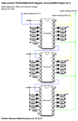
and this is how i connect the TPIC6C595:

Thank you for helping!
Can you please post a link to the specs of these LEDs?

It means "positive". The higher voltage wire from your power supply.

"-ve" means "negative". The lower voltage wire from your power supply.

You need a bypass capacitor for each chip. 0.1uF ceramic.

Start with something simple, less fancy.

See the bit where it says +5 in your diagram, then connect it to +12 instead.

What sort of course are you doing that a Uni will let you start a project without knowing what +5 means?

As asked of you before can you post a link to these LEDs as we need to know before we can recommend a value for the resistor to use.

1 Like

i know what 5v means! for this part and just to test the shift register i am trying to use simple 5v leds as i said

yea makes sense, thanks!

In which case we need to see how you are connecting the TPIC6C59N to your Arduino. Code means nothing without knowing what it is driving.

Also just stick to one shift register first.

No it doesn't.
It is the latch pin, and transfers the internal state of the shift register to the outputs. It should be connect to all shift registers.

No it doesn't, as far as I can see this line is a nonsense.

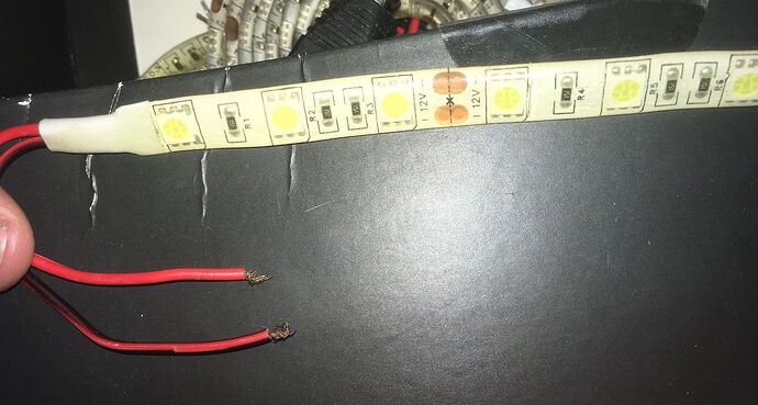
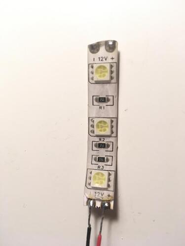
sorry i dont have the specs because these were my brothers from an old project of his but i believe they are just simple 12v led strips

You are very very wrong. These are not independent LEDs and they can't be driven with a TPIC6C59N at all.

They are in fact WS2812b LEDs fitted in groups of 3 in seriese which is where the 12V spec comes from.

i didn't write this code, its just one i found that works with the 74HC595N and i was hoping would work with the TPIC6C59N also, but thank you for pointing out what doesn't make sense

i know they are in groups of three and i planned to cut them in groups of three and control each of those groups individually creating a matrix, so you are saying its impossible to do that with TPIC6C59N? thank you for the help and for your time!

It is tpic6c595, not tpic6c59.

Each output pin of the chip can drive a strip of at least 3 LEDs using a 12V supply. Maybe an output pin can drive a strip of 9 LEDs, but it depends on the strip, and it is difficult to know from the photos.

yes sorry my mistake

is this better?

thank you!

Yes you can't drive this strip with a shift register of any description. You need to use a library to generate the sequence of pulses required to drive the LEDs. Popular is the Fast LED library and Adafruit's Neopixel Library.

You are best using longer strips and arranging them in a zigzag pattern to form your matrix, although the aspect ratio of the matrix will be three to one. Is that acceptable? If not get a normal 5V strip of Neopixels from any supplier. The high the density, that is the pixels per inch, the more square will be your matrix pixels.

Search for the many examples of LED strip to matrix tutorials.

Thank you. I am starting to think its better to buy 500 of these kind of little leds (which is actually really cheap) and control them with the 74HC595N, that would be possible right?

https://mauser.pt/catalog/product_info.php?products_id=017-0210&utm_source=google&utm_medium=cpc&utm_campaign=shopping_catalog_pt_011&utm_content=feed&gad_source=1&gclid=Cj0KCQiA3uGqBhDdARIsAFeJ5r2TtIyHXl12R_uEVpKreRhq6vvD0aCw7PWA0pyxW0XgDNo_RmDSPekaAuKKEALw_wcB

There should be a 3rd wire for the data if they were addressable LEDs. Where did that go?