Matrix help hub75 - Got this code

Got this code on github, from majsatic, however will not work all the way for me am I missing something

/******************************************************************************
    -------------------------------------------------------------------------
    Steps to create a virtual display made up of a chain of panels in a grid
    -------------------------------------------------------------------------

    Read the documentation!
    https://github.com/mrfaptastic/ESP32-HUB75-MatrixPanel-DMA/tree/master/examples/ChainedPanels

    tl/dr:
    
    - Set values for NUM_ROWS, NUM_COLS, PANEL_RES_X, PANEL_RES_Y, PANEL_CHAIN_TYPE. 

    - Other than where the matrix is defined and matrix.begin in the setup, you 
      should now be using the virtual display for everything (drawing pixels, writing text etc).
       You can do a find and replace of all calls if it's an existing sketch
      (just make sure you don't replace the definition and the matrix.begin)

    - If the sketch makes use of MATRIX_HEIGHT or MATRIX_WIDTH, these will need to be 
      replaced with the width and height of your virtual screen. 
      Either make new defines and use that, or you can use virtualDisp.width() or .height()

*****************************************************************************/
// 1) Include key virtual display library
    #include <ESP32-VirtualMatrixPanel-I2S-DMA.h>

// 2) Set configuration
    #define NUM_ROWS 2 // Number of rows of chained INDIVIDUAL PANELS
    #define NUM_COLS 2 // Number of INDIVIDUAL PANELS per ROW
    #define PANEL_RES_X 64 // Number of pixels wide of each INDIVIDUAL panel module. 
    #define PANEL_RES_Y 32 // Number of pixels tall of each INDIVIDUAL panel module.
    #define PANEL_CHAIN NUM_ROWS*NUM_COLS // total number of panels chained one to another

    /* Configure the serpetine chaining approach. Options are:
        CHAIN_TOP_LEFT_DOWN
        CHAIN_TOP_RIGHT_DOWN
        CHAIN_BOTTOM_LEFT_UP
        CHAIN_BOTTOM_RIGHT_UP

        The location (i.e. 'TOP_LEFT', 'BOTTOM_RIGHT') etc. refers to the starting point where 
        the ESP32 is located, and how the chain of panels will 'roll out' from there.

        In this example we're using 'CHAIN_BOTTOM_LEFT_UP' which would look like this in the real world:

        Chain of 4 x 64x32 panels with the ESP at the BOTTOM_LEFT:

        +---------+---------+
        |    4    |    3    |
        |         |         |
        +---------+---------+
        |    1    |    2    |
        |  (ESP)  |         |
        +---------+---------+      

    */
    #define VIRTUAL_MATRIX_CHAIN_TYPE CHAIN_BOTTOM_RIGHT_UP 

// 3) Create the runtime objects to use

    // placeholder for the matrix object
    MatrixPanel_I2S_DMA *dma_display = nullptr;

    // placeholder for the virtual display object
    VirtualMatrixPanel  *virtualDisp = nullptr;


/******************************************************************************
 * Setup!
 ******************************************************************************/
void setup() {
  
  delay(2000);
  Serial.begin(115200);
  Serial.println(""); Serial.println(""); Serial.println("");
  Serial.println("*****************************************************");
  Serial.println(" HELLO !");
  Serial.println("*****************************************************");
 
  /******************************************************************************
   * Create physical DMA panel class AND virtual (chained) display class.   
   ******************************************************************************/

  /*
    The configuration for MatrixPanel_I2S_DMA object is held in HUB75_I2S_CFG structure,
    All options has it's predefined default values. So we can create a new structure and redefine only the options we need

	Please refer to the '2_PatternPlasma.ino' example for detailed example of how to use the MatrixPanel_I2S_DMA configuration
  */

  HUB75_I2S_CFG mxconfig(
                PANEL_RES_X,   // module width
                PANEL_RES_Y,   // module height
                PANEL_CHAIN    // chain length
  );

  //mxconfig.driver = HUB75_I2S_CFG::FM6126A;     // in case that we use panels based on FM6126A chip, we can set it here before creating MatrixPanel_I2S_DMA object

  // Sanity checks
  if (NUM_ROWS <= 1) {
    Serial.println(F("There is no reason to use the VirtualDisplay class for a single horizontal chain and row!"));
  }

  // OK, now we can create our matrix object
  dma_display = new MatrixPanel_I2S_DMA(mxconfig);

  // let's adjust default brightness to about 75%
  dma_display->setBrightness8(250);    // range is 0-255, 0 - 0%, 255 - 100%

  // Allocate memory and start DMA display
  if( not dma_display->begin() )
      Serial.println("****** !KABOOM! I2S memory allocation failed ***********");

  // create VirtualDisplay object based on our newly created dma_display object
  virtualDisp = new VirtualMatrixPanel((*dma_display), NUM_ROWS, NUM_COLS, PANEL_RES_X, PANEL_RES_Y, VIRTUAL_MATRIX_CHAIN_TYPE);

  // So far so good, so continue
  virtualDisp->fillScreen(virtualDisp->color444(0, 0, 0));
  virtualDisp->drawDisplayTest(); // draw text numbering on each screen to check connectivity

 // delay(1000);

  Serial.println("Chain of 4x 64x32 panels for this example:");
  Serial.println("+---------+---------+");
  Serial.println("|    4    |    3    |");
  Serial.println("|         |         |");
  Serial.println("+---------+---------+");
  Serial.println("|    1    |    2    |");
  Serial.println("| (ESP32) |         |");
  Serial.println("+---------+---------+");

   // draw blue text
   virtualDisp->setFont(&FreeSansBold12pt7b);
   virtualDisp->setTextColor(virtualDisp->color565(0, 0, 255));
   virtualDisp->setTextSize(2); 
   virtualDisp->setCursor(0, virtualDisp->height()- ((virtualDisp->height()-45)/2));    
   virtualDisp->print("THIS");

   // Red text inside red rect (2 pix in from edge)
   virtualDisp->drawRect(1,1, virtualDisp->width()-2, virtualDisp->height()-2, virtualDisp->color565(255,0,0));

   // White line from top left to bottom right
   virtualDisp->drawLine(0,0, virtualDisp->width()-1, virtualDisp->height()-1, virtualDisp->color565(255,255,255));

   virtualDisp->drawDisplayTest(); // re draw text numbering on each screen to check connectivity
   
}

void loop() {
  

} // end loop


/*****************************************************************************

    Thanks to:

    * Brian Lough for the original example as raised in this issue:
      https://github.com/mrfaptastic/ESP32-HUB75-MatrixPanel-I2S-DMA/issues/26

      YouTube: https://www.youtube.com/brianlough
      Tindie: https://www.tindie.com/stores/brianlough/
      Twitter: https://twitter.com/witnessmenow

    * Galaxy-Man for the kind donation of panels make/test that this is possible:
      https://github.com/Galaxy-Man

*****************************************************************************/

since I am still way to new to figure out the problems if i can get pointed to the right area that would be helpfull.

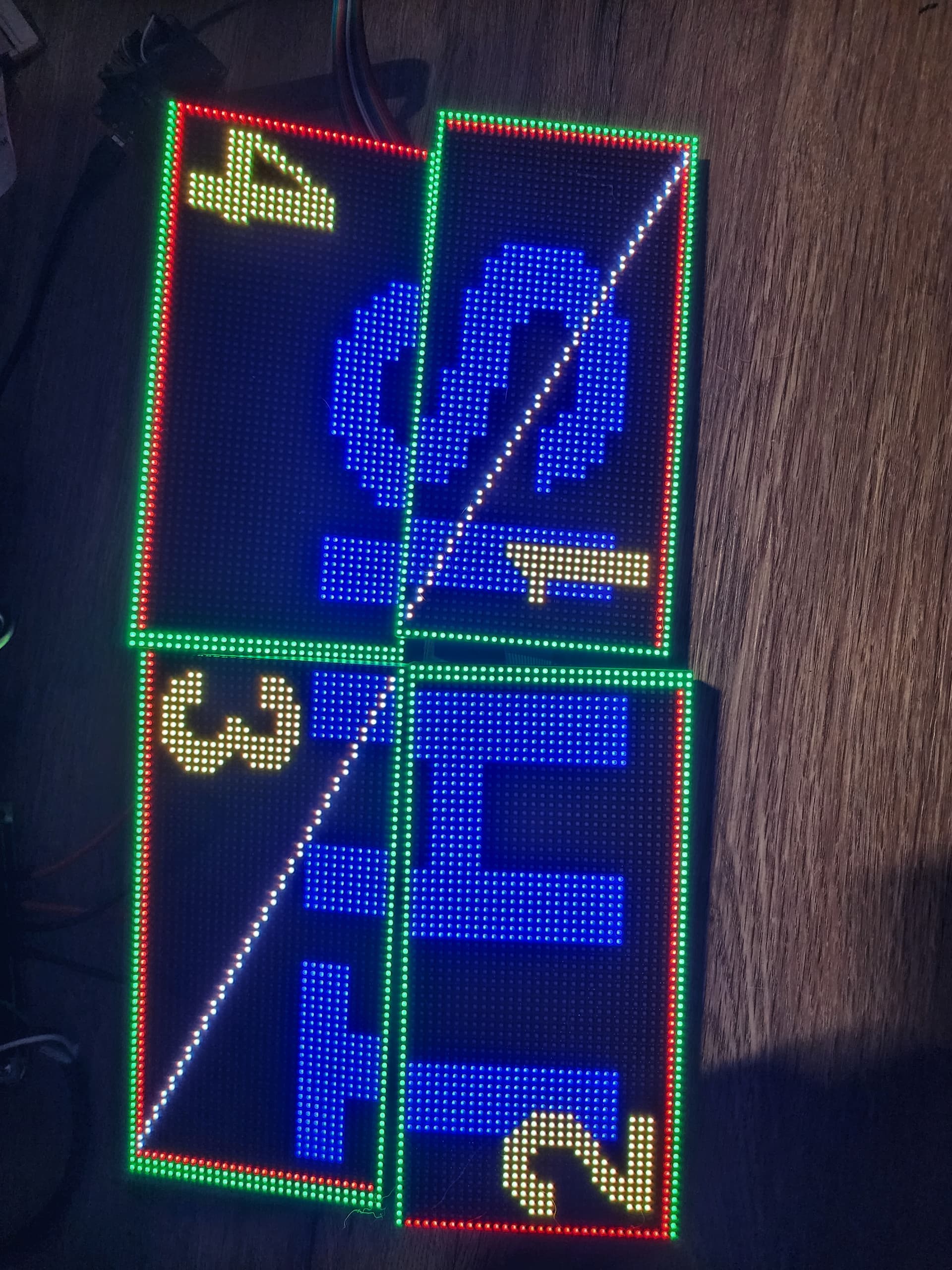
as can be seen the grid works fine except that grids 2-4 are off one pixel no matter if I switch the panels around.

Please, remove the code tags from around your final comment for easier reading.

Would you hand-draw what you you expect (where the color lines/rects go) versus what you see on each panel? "Off one pixel" can be anything,

Observing/guessing here; resizing your panels with -1 or -2 might not change the origin (0,0), that is to say, the re-sized height and width might have the same starting point... and "-1" will create an odd number of rows/columns... you might need to resize in even numbers, -2, -4, et c.

supposed to be green box outline, red box covering all 4

like picture above but for 4 panels just cant get help from original site

The original in Post #3 shows the "feet" of 1 and 2 touching the "feet" of "6 and 5" (4 and 3 for you). You have the "head" of 2 and 1 touching the "head" of 3 and 4.

Thank you XFPD for your time.

Yes that is correct on how it would have been setup, how ever I will just put them end to end for a 4 chain length now I just need to find where I can find out how to send text and images to it from program vixen lights. I am having a hard time finding the documentation. I will keep looking this test program works just find to make it length.

/*
 * Portions of this code are adapted from Aurora: https://github.com/pixelmatix/aurora
 * Copyright (c) 2014 Jason Coon
 *
 * Portions of this code are adapted from LedEffects Plasma by Robert Atkins: https://bitbucket.org/ratkins/ledeffects/src/26ed3c51912af6fac5f1304629c7b4ab7ac8ca4b/Plasma.cpp?at=default
 * Copyright (c) 2013 Robert Atkins
 *
 * Permission is hereby granted, free of charge, to any person obtaining a copy of
 * this software and associated documentation files (the "Software"), to deal in
 * the Software without restriction, including without limitation the rights to
 * use, copy, modify, merge, publish, distribute, sublicense, and/or sell copies of
 * the Software, and to permit persons to whom the Software is furnished to do so,
 * subject to the following conditions:
 *
 * The above copyright notice and this permission notice shall be included in all
 * copies or substantial portions of the Software.
 *
 * THE SOFTWARE IS PROVIDED "AS IS", WITHOUT WARRANTY OF ANY KIND, EXPRESS OR
 * IMPLIED, INCLUDING BUT NOT LIMITED TO THE WARRANTIES OF MERCHANTABILITY, FITNESS
 * FOR A PARTICULAR PURPOSE AND NONINFRINGEMENT. IN NO EVENT SHALL THE AUTHORS OR
 * COPYRIGHT HOLDERS BE LIABLE FOR ANY CLAIM, DAMAGES OR OTHER LIABILITY, WHETHER
 * IN AN ACTION OF CONTRACT, TORT OR OTHERWISE, ARISING FROM, OUT OF OR IN
 * CONNECTION WITH THE SOFTWARE OR THE USE OR OTHER DEALINGS IN THE SOFTWARE.
 */
 

// HUB75E pinout
// R1 | G1
// B1 | GND
// R2 | G2
// B2 | E
//  A | B
//  C | D
// CLK| LAT
// OE | GND

/*  Default library pin configuration for the reference
  you can redefine only ones you need later on object creation

#define R1 25 
#define G1 26
#define BL1 27
#define R2 14
#define G2 12
#define BL2 13
#define CH_A 23
#define CH_B 19
#define CH_C 5
#define CH_D 17
#define CH_E -1 // assign to any available pin if using two panels or 64x64 panels with 1/32 scan
#define CLK 16
#define LAT 4
#define OE 15

*/


#include <ESP32-HUB75-MatrixPanel-I2S-DMA.h>
#include <FastLED.h>

// Configure for your panel(s) as appropriate!
#define PANEL_WIDTH 64
#define PANEL_HEIGHT 32  	// Panel height of 64 will required PIN_E to be defined.  
#define PANELS_NUMBER 4 	// Number of chained panels, if just a single panel, obviously set to 1  ******  TOTAL OF 8192 Pixels 64*32*4
#define PIN_E 32

#define PANE_WIDTH PANEL_WIDTH * PANELS_NUMBER
#define PANE_HEIGHT PANEL_HEIGHT


// placeholder for the matrix object
MatrixPanel_I2S_DMA *dma_display = nullptr;


uint16_t time_counter = 0, cycles = 0, fps = 0;
unsigned long fps_timer;

CRGB currentColor;
CRGBPalette16 palettes[] = {HeatColors_p, LavaColors_p, RainbowColors_p, RainbowStripeColors_p, CloudColors_p};
CRGBPalette16 currentPalette = palettes[0];


CRGB ColorFromCurrentPalette(uint8_t index = 0, uint8_t brightness = 255, TBlendType blendType = LINEARBLEND) {
  return ColorFromPalette(currentPalette, index, brightness, blendType);
}

void setup() {
  
  Serial.begin(115200);
  
  Serial.println(F("*****************************************************"));
  Serial.println(F("*        ESP32-HUB75-MatrixPanel-I2S-DMA DEMO       *"));
  Serial.println(F("*****************************************************"));

  /*
    The configuration for MatrixPanel_I2S_DMA object is held in HUB75_I2S_CFG structure,
    pls refer to the lib header file for full details.
    All options has it's predefined default values. So we can create a new structure and redefine only the options we need 

    // those are the defaults
    mxconfig.mx_width = 64;                   // physical width of a single matrix panel module (in pixels, usually it is always 64 ;) )
    mxconfig.mx_height = 32;                  // physical height of a single matrix panel module (in pixels, usually almost always it is either 32 or 64)
    mxconfig.chain_length = 1;                // number of chained panels regardless of the topology, default 1 - a single matrix module
    mxconfig.gpio.r1 = R1;                    // pin mappings
    mxconfig.gpio.g1 = G1;
    mxconfig.gpio.b1 = B1;                    // etc
    mxconfig.driver = HUB75_I2S_CFG::SHIFT;   // shift reg driver, default is plain shift register
    mxconfig.double_buff = false;             // use double buffer (twice amount of RAM required)
    mxconfig.i2sspeed = HUB75_I2S_CFG::HZ_10M;// I2S clock speed, better leave as-is unless you want to experiment
  */

  /*
    For example we have two 64x64 panels chained, so we need to customize our setup like this

  */
  HUB75_I2S_CFG mxconfig;
  mxconfig.mx_height = PANEL_HEIGHT;      // we have 64 pix heigh panels
  mxconfig.chain_length = PANELS_NUMBER;  // we have 2 panels chained
  mxconfig.gpio.e = PIN_E;                // we MUST assign pin e to some free pin on a board to drive 64 pix height panels with 1/32 scan
  //mxconfig.driver = HUB75_I2S_CFG::FM6126A;     // in case that we use panels based on FM6126A chip, we can change that

  /*
    //Another way of creating config structure
    //Custom pin mapping for all pins
    HUB75_I2S_CFG::i2s_pins _pins={R1, G1, BL1, R2, G2, BL2, CH_A, CH_B, CH_C, CH_D, CH_E, LAT, OE, CLK};
    HUB75_I2S_CFG mxconfig(
                            64,   // width
                            64,   // height
                             4,   // chain length
                         _pins,   // pin mapping
      HUB75_I2S_CFG::FM6126A      // driver chip
    );

  */


  // OK, now we can create our matrix object
  dma_display = new MatrixPanel_I2S_DMA(mxconfig);

  // let's adjust default brightness to about 75%
  dma_display->setBrightness8(255);    // range is 0-255, 0 - 0%, 255 - 100%

  // Allocate memory and start DMA display
  if( not dma_display->begin() )
      Serial.println("****** !KABOOM! I2S memory allocation failed ***********");
 
  // well, hope we are OK, let's draw some colors first :)
  Serial.println("Fill screen: RED");
  dma_display->fillScreenRGB888(255, 0, 0);
  delay(1000);

  Serial.println("Fill screen: GREEN");
  dma_display->fillScreenRGB888(0, 255, 0);
  delay(1000);

  Serial.println("Fill screen: BLUE");
  dma_display->fillScreenRGB888(0, 0, 255);
  delay(1000);

  Serial.println("Fill screen: Neutral White");
  dma_display->fillScreenRGB888(255, 255, 255);
  delay(1000);

  Serial.println("Fill screen: black");
  dma_display->fillScreenRGB888(0, 0, 0);
  delay(1000);


  // Set current FastLED palette
  currentPalette = RainbowColors_p;
  Serial.println("Starting plasma effect...");
  fps_timer = millis();
}

void loop() {
  
    for (int x = 0; x < PANE_WIDTH; x++) {
            for (int y = 0; y <  PANE_HEIGHT; y++) {
                int16_t v = 128;
                uint8_t wibble = sin8(time_counter);
                v += sin16(x * wibble * 3 + time_counter);
                v += cos16(y * (128 - wibble)  + time_counter);
                v += sin16(y * x * cos8(-time_counter) / 8);

                currentColor = ColorFromPalette(currentPalette, (v >> 8)); //, brightness, currentBlendType);
                dma_display->drawPixelRGB888(x, y, currentColor.r, currentColor.g, currentColor.b);
            }
    }

    ++time_counter;
    ++cycles;
    ++fps;

    if (cycles >= 1024) {
        time_counter = 0;
        cycles = 0;
        currentPalette = palettes[random(0,sizeof(palettes)/sizeof(palettes[0]))];
    }

    // print FPS rate every 5 seconds
    // Note: this is NOT a matrix refresh rate, it's the number of data frames being drawn to the DMA buffer per second
    if (fps_timer + 5000 < millis()){
      Serial.printf_P(PSTR("Effect fps: %d\n"), fps/5);
      fps_timer = millis();
      fps = 0;


    }
} // end loop

with the panels looking correct. just gonna make it like a message board at certain points.