Matrix keyboard help

Hi:

I'm working on a matrix switch (4x3) made with some blue switches I had lying around. I'm using the Arduino pro micro

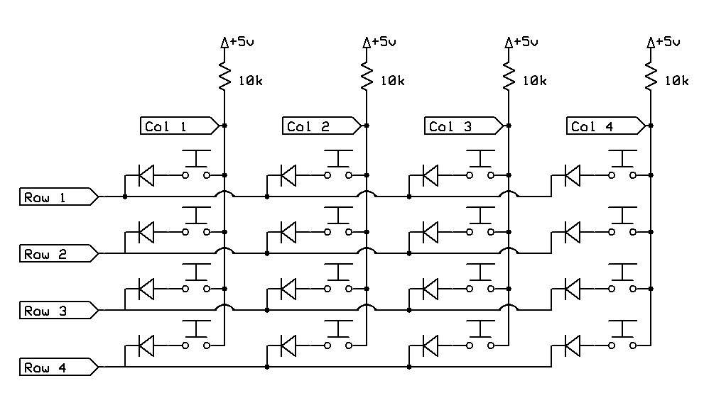
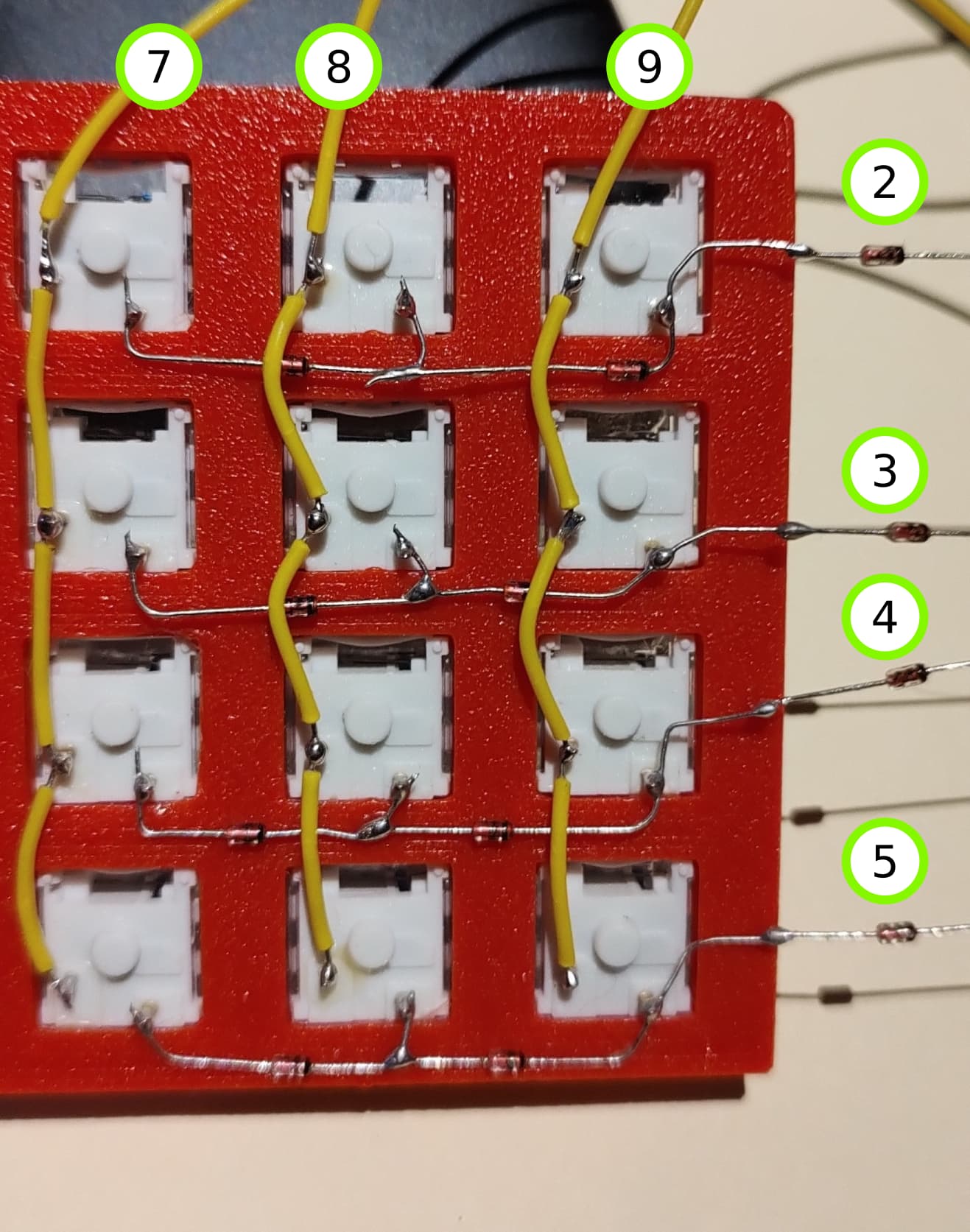
Here's a picture of the wiring, I'm using 1N4148 diodes for the rows connections, the green circles indicate to which Arduino pins every row/col are connected.

And here's my code:

#include <Keypad.h>

const byte ROWS = 4;
const byte COLS = 3;

char keys[ROWS][COLS] =
{
  {'1', '2', '3',},
  {'4', '5', '6',},
  {'7', '8', '9',},
  {'A', 'B', 'C'}
};

byte colPins[COLS] = {7,8,9}; //column pins
byte rowPins[ROWS] = {2, 3, 4, 5}; //row pins

Keypad keypad = Keypad( makeKeymap(keys), rowPins, colPins, ROWS, COLS );

void setup()
{
  Serial.begin(115200);
  delay(1500);
  Serial.println("init ok ...");
}

void loop()
{
  char key = keypad.getKey();
  if (key)
  {
    Serial.print("key : ");
    Serial.println(key);
  }
}

Code compiles/uploads ok, but nothing happens when I press a key.

Here's what I've tried:

1- Adding these lines to the setup() routine:

  pinMode(7, INPUT_PULLUP);
  pinMode(8, INPUT_PULLUP);
  pinMode(9, INPUT_PULLUP);

Same result: nothing happens when switch is pressed.

2- Continuity tested columns wiring, each individual switch and they work. Rows wiring also pass continuity test when pressed.

3- Measure if any voltage was detected in the row connection (start and end point) when a switch is pressed: my multi-meter goes from 0 to around 0.11~0.13 V. I don't know if this is ok.

My guess is I need to connect some ground or maybe even set columns to HIGH? but I want to avoid magic smoke so I thought asking here first. Any help will be much appreciated.

Pretty new to arduino.

  • Check each wire to see if it is touching and connecting
  • Maybe you need to int or define the pins I really don't know
  • Also if you just put input, then there is no output or vice versa, so I would check on that to make sure you have a code that actually shows the button getting pressed and that stuff
  • Also whats a matrix grid?
  • If you are trying to achieve anti ghosting, wire the diodes as seen on this 4X4 keypad.

1 Like

Ok, thanks for the schematic and yes! I want to prevent ghosting... maybe I'm reading it wrong but as far as I see the diodes in my wiring are ok? diode arrow means the mark on the physical diode, right?

But what I see is different is that columns have a resistor and also 5v+, I guess that's what's missing on my code... does that mean that I have to set the column pins as output and set them as HIGH? can someone please confirm this?

Yeah I did, all wires seem to be ok, I believe it's the pin definition in the code that's wrong

Your wiring does not match what is being shown in LarryD’s diagram. Look at it more closely.

1 Like

Ok I see, so I need to run an horizontal line and then connect the diodes to that common line, right? ... also, the resistors on the columns are not required because as far as I know arduino has internal resistors?

Correct

1 Like

As @HazardsMind pointed out, my wiring was not reflecting this schematic, I re wired it and directly coded the logic instead of using Keypad.h library and it's working like a charm, thanks both of you

1 Like

This topic was automatically closed 180 days after the last reply. New replies are no longer allowed.