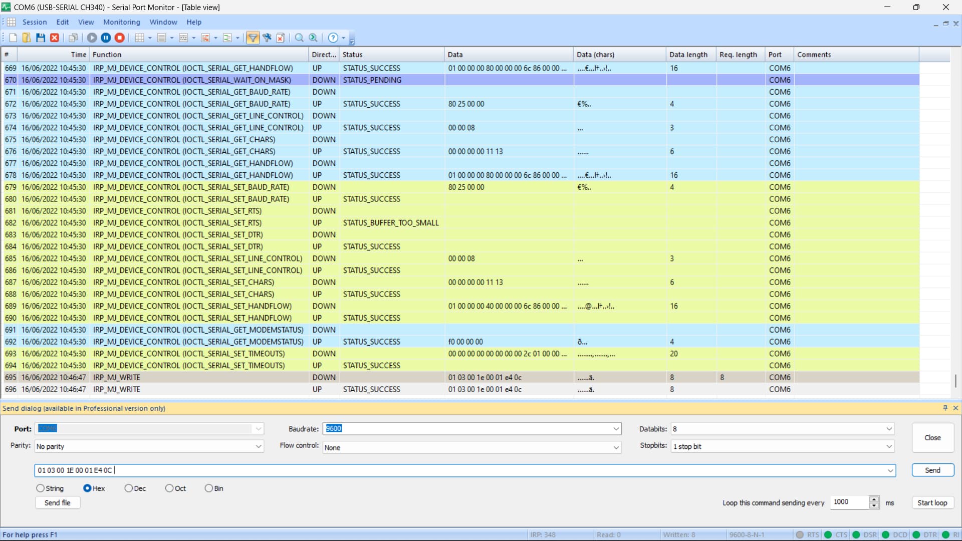

The top screenshot seems to show the correct data being transmitted. The bottom screenshot seems to show the wrong data being transmitted - the final byte looks wrong.
I'm at a loss as to what suggest next.
In both the response was same ä. In 1st screenshot check the last line response.
Looking back through your posts, I didnt ask what adapter you were using on your laptop to talk to the sensor.
This is the adapter im using
Ok. That's a 2-pin RS-485 dongle from memory. I don't know how you get a ground connection using one of those.
Long shot, but have you tried swapping the A and B wires over just in case they are the wrong way round?
@markd833 I gave supply from a 12V source. And I also tried interchanging the A & B. I got same result.
We've taken the Arduino out of the equation, so we know it's not a code issue.
If we assume that the PC applications are behaving correctly, and you've swapped A & B over and still not been able to communicate with the NPK sensor with a simple PC app, then I'm at the limit of my knowledge on what the problem could be.
Okay @markd833. I will try to figure it out. If I get a solution I will be sharing it here. Thanks for the help ![]() .
.
Hi everyone, i might have solved the issue of having the response 255 for the NPK sensor. All you have to do is, under the void setup, for mod.begin(9600), change the baud rate for mod.begin to 4800, meaning mod.begin(4800). Whats happening is that some of the sensors, i am assuming those NPK which are rated for 5V, they are already designed for baud rate 4800. So, just make this small change from existing codes and it would work like a charm.
2 Likes
Hello guys,
I have bought some of those sensors (7 in 1 soil sensor), but i have trouble with the HEX addresses.
I have read the posts carefully, but I just dont get it, how to display all the values on the Arduino.
Does anyone has the source code to read all the sensors?
Thank you and with best regards
Do you have a datasheet for your particular sensor. There's a chance that the registers may be slightly different to the basic NPK sensor that gets discussed here.
What's the trouble?
Start by trying to read 1 value rather than going all in.
Which Arduino are you using?
Which RS-485 module are you using?
How have you connected your Arduino, RS-485 module and NPK sensor together?
Do you have a USB-RS485 dongle that you can use on a PC to check the Modbus comms?
-
Yes, I have, but can't upload many files, because I'm a "new user"

-
How do i get the HEX numbers of the different sensors, or how do I read them? As of the code example:
const byte nitro[] = {0x01, 0x03, 0x00, 0x1e, 0x00, 0x01, 0xe4, 0x0c};
const byte phos[] = {0x01, 0x03, 0x00, 0x1f, 0x00, 0x01, 0xb5, 0xcc};
const byte pota[] = {0x01, 0x03, 0x00, 0x20, 0x00, 0x01, 0x85, 0xc0};
I know that 0x01 is the address code, 0x03 is function code, 0x00 is the start address, which in my knowledge is fixed.
The rest on the other side is a mystery! How do I get 0x1e; 0x1f; 0x20? And also the low check code and high check code?
- I tried few things and some did work.
The first Arduino would be on UNO, later when i got other parts of my project, i would like to switch on the MEGA.
I am using the max485ttl between the Arduino and the sensor.
For the moment I don't have an USB dongle to test it, but I'm sure on PC won't be much a problem to get it work.
My goal is, to have all the sensors at once working and as accurate as possible.
Thank you very much for trying to help me!
With best regards M0iN94
Edit: 1. the link to the datasheet provided by my seller: Upload files for free - 五插针土壤变送器(485型).doc - ufile.io
Ok, so that array, say the nitro one, is a pre set fixed modbus message. You are correct about the 0x01 being the address and 0x03 being the function code.
The start register (or address) is 2 bytes and is the 0x00 + 0x1e (= 0x001e). The next 2 bytes are the count of the number of registers (or addresses) to return. In this case it's 0x00 + 0x01 (= 0x0001). So 1 16-bit data word will be returned by the slave. The 0xe4 + 0x0c are a 16-bit CRC16 checksum for the message.
Cool, okay I think I got that part, about the additions of the bytes.
But how do I get that 0x1e ![]()

I see on that paet of the datasheet the register address on the left side.
But the example later on that sheet confuses me (it's an example that shows 4 sensor at once working).
Thanks and with best regards
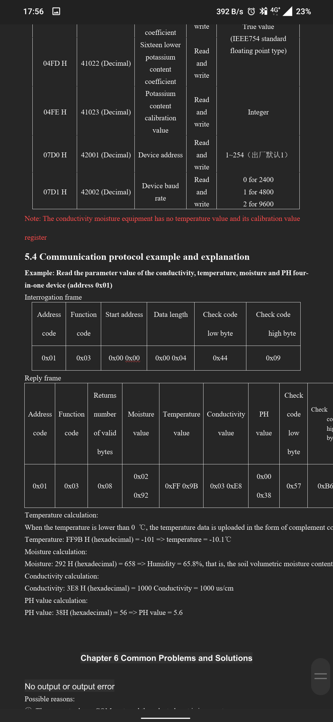

The worked example is as I described back in post #95. Your sensor has a different register layout to the standard NPK sensor.
The example is telling the sensor to send 4 words starting from address 0000. Your image shows (left hand column) the addresses and you can see what parameters are held in registers 0000, 0001, 0002 & 0003.
So, would it be like this:
const byte moist[] = {0x01, 0x03, 0x00, 0x00, 0x00, 0x01, 0x??, 0x??};
?
What's the low and high check sum of the crc16?
How do I calculate that one?
Thanks again
Yes, if you want the sensor to return 1 word from address 0x0000. To calculate the checksum, I recommend going to crccalc.com and selecting CRC16, entering your values and reading the modbus checksum it calculates for you.
EDIT: Here's an example of how to calculate the checksum using the nitro message:
const byte nitro[] = {0x01, 0x03, 0x00, 0x1e, 0x00, 0x01, 0xe4, 0x0c};
Go to crccalc.com, select HEX as the input and output. Type in the 6 bytes of the message and click on the CRC-16 button. The web page should look something like this:

Scroll down the page till you find the CRC-16/MODBUS line. Note the 16-bit value 0x0CE4 in the darker shaded box. That's the value you want.
Look at the canned nitro message and you can see the 0x0C and 0xE4 values - note that they are swapped around (lower byte first).
You can use this technique to calculate the Modbus CRC for any of your pre-defined messages you need.