MAX7219 and MAX7221 driving me insane

I'm rebuilding e pinball machine from the 70s which has four 7segment scores displays, and since it's not possible to buy processors, memories and eproms from that particular era, I decided to rebuild it with recent electronics, namely an Arduino Mega to control the switches and solenoids, and 3 nanos to control the sound, lights and score boards.

I thought the score board would be easy, since I decided to make new PCBs matching the old ones, but with MAX7219 ICs for simplicity. Did some tests in the breadboard without a problem, but after assembling the material in the PCBs they show garbage after some time.

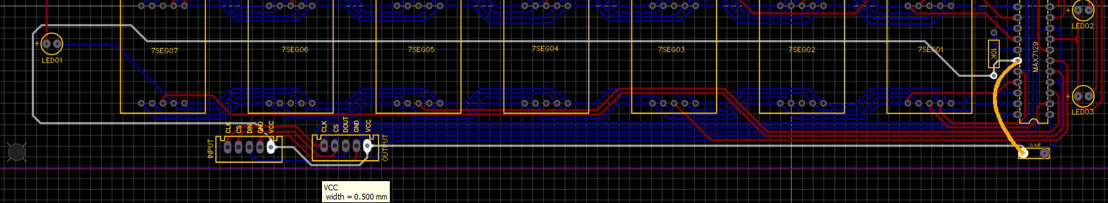
This is the initial circuit. The 6 score boards where connected to each other and the first to the Arduino nano with a 1 (40 inches) meter cable. In this configuration the first score board works but stops working after a while, but the 3rd and 4th don't work a all. So my tests where only with the first score board.

As someone suggested in another topic, I had pull up registers to the CLK, CS and DIN to help minimize the capacitance of the cables. That seemed to help a little, but problem persists.

Well... the MAX7219 has a brother designed to deal with this problems, so I bought the MAX7221 to replace these. Assembled another board with the MAX7221, since those are supposed to be a direct replacement, but it didn't work at all. Not even a single led lit.

Back to the breadboard... It works flawlessly. And back to the PCB, with only one 7 Segment to try to isolate the problem... Nothing. WTF????

Maybe it's a problem in the PCB? Checked everything. It's exactly like the schematic... and it worked with the 7219. I really don't know what to try next.

Also, I tried every single code for the Arduino I found on the net and the problem is always the same.

/*
  Basic code for using Maxim MAX7219/MAX7221 with Arduino.

  Wire the Arduino and the MAX7219/MAX7221 together as follows:

  | Arduino   | MAX7219/MAX7221 |
  | --------- | --------------- |
  | MOSI (11) | DIN (1)         |
  | SCK (13)  | CLK (13)        |
  | I/O (7)*  | LOAD/CS (12)    |

    * - This should match the LOAD_PIN constant defined below.
  
  For the rest of the wiring follow the wiring diagram found in the datasheet.
  
  Datasheet: http://datasheets.maximintegrated.com/en/ds/MAX7219-MAX7221.pdf

  Author:  Nicholas Dobie <nick@nickdobie.com>
  Date:    30 December 2013
  License: WTFPL (http://www.wtfpl.net/)
 */
#include <SPI.h>

// What pin on the Arduino connects to the LOAD/CS pin on the MAX7219/MAX7221
#define LOAD_PIN 7

/**
 * Transfers data to a MAX7219/MAX7221 register.
 * 
 * @param address The register to load data into
 * @param value   Value to store in the register
 */
void maxTransfer(uint8_t address, uint8_t value) {

  // Ensure LOAD/CS is LOW
  digitalWrite(LOAD_PIN, LOW);

  // Send the register address
  SPI.transfer(address);

  // Send the value
  SPI.transfer(value);

  // Tell chip to load in data
  digitalWrite(LOAD_PIN, HIGH);
}
  

void setup() {
  
  // Set load pin to output
  pinMode(LOAD_PIN, OUTPUT);

  // Reverse the SPI transfer to send the MSB first  
  SPI.setBitOrder(MSBFIRST);
  
  // Start SPI
  SPI.begin();

  // Run test
  // All LED segments should light up
  maxTransfer(0x0F, 0x01);
  delay(1000);
  maxTransfer(0x0F, 0x00);
  
  // Enable mode B
  maxTransfer(0x09, 0xFF);
  
  // Use lowest intensity
  maxTransfer(0x0A, 0x00);
  
  // Only scan one digit
  maxTransfer(0x0B, 0x07);
  
  // Turn on chip
  maxTransfer(0x0C, 0x01);


}

void loop() {
  
  // Loop through each code
  for (uint8_t i = 0; i < 0x10; ++i)
  {
    maxTransfer(0x01, i);
    maxTransfer(0x02, i);
    maxTransfer(0x03, i);
    maxTransfer(0x04, i);
    maxTransfer(0x05, i);
    maxTransfer(0x06, i);
    maxTransfer(0x07, i);
    maxTransfer(0x08, i);
    delay(100);
    
  }
  
}

EDIT1: Add PCB Drawing

The 10uF is missing there, but I added it in the back of the PCB.

EDIT2:


+5V PIN


DIN


CS


CLK

post full schematic and board layout files

Hi Kolaha, I edited the main post to include the PCB layout. I don't have a full schematic.

I see three areas that could be problems/issues.

SPI over long cables.

Running the IC at it's max power dissipation.

No ground planes on the PCB.

SPI speed and power diipation are probably your biggest problems

did you draw layout manually?
upload layout file, not picture.

btw, sketch works.

Manually. It was simple enough. Here is the layout for EasyEda
PCB_Score Display_2023-06-14.zip (34.4 KB)

SCH_MAX7219 8x8 matrix_2023-06-14.zip (9.8 KB)
schematic is simple too

Drive Common-Cathode LED Display

LED01-03 opposite direction.
what 7seg display do you get?

Regarding the long wires, I tried SPI at lowest speed. No change.
Also, add pull-up resistors to minimize the wire capacitance. No change.
Now testing with 15cm wires and the board with MAX7221 still doesn't work. It cannot be that.

Running the IC at it's max power could be the problem, but now I'm testing with only one 7 segment display. The MAX7221 refuses to work, although it works with flaws with the MAX7219. Also tried with the lowest brightness in the 7segments. No luck.

The ground planes... I've should include them... But do you think it could cause this issue? Seems unlikely, but since I've tested everything else...

If nothing works, I'll make another PCB version with the planes and some more changes. I don't want to do that without knowing for sure what the problem is. Do you know any way to test that?

I made changes to your code.
Try this:

/*
  Basic code for using Maxim MAX7219/MAX7221 with Arduino.

  Wire the Arduino and the MAX7219/MAX7221 together as follows:

  | Arduino   | MAX7219/MAX7221 |
  | --------- | --------------- |
  | MOSI (11) | DIN (1)         |
  | SCK (13)  | CLK (13)        |
  | I/O (7)*  | LOAD/CS (12)    |

    * - This should match the LOAD_PIN constant defined below.
  
  For the rest of the wiring follow the wiring diagram found in the datasheet.
  
  Datasheet: http://datasheets.maximintegrated.com/en/ds/MAX7219-MAX7221.pdf

  Author:  Nicholas Dobie <nick@nickdobie.com>
  Date:    30 December 2013
  License: WTFPL (http://www.wtfpl.net/)
 */
#include <SPI.h>

// What pin on the Arduino connects to the LOAD/CS pin on the MAX7219/MAX7221
#define LOAD_PIN 7

/**
 * Transfers data to a MAX7219/MAX7221 register.
 * 
 * @param address The register to load data into
 * @param value   Value to store in the register
 */
void maxTransfer(uint8_t address, uint8_t value) {

  // Ensure LOAD/CS is LOW
  digitalWrite(LOAD_PIN, LOW);
  delay(5);

  // Send the register address
  SPI.transfer(address);

  // Send the value
  SPI.transfer(value);
  delay(5);

  // Tell chip to load in data
  digitalWrite(LOAD_PIN, HIGH);
}
  
void setup() {
  
  // Set load pin to output
  pinMode(LOAD_PIN, OUTPUT);
	
  // Start SPI
  SPI.begin();
  SPI.beginTransaction(SPISettings(250000, MSBFIRST, SPI_MODE0));

  // Run test
  // All LED segments should light up
  maxTransfer(0x0F, 0x01);
  delay(1000);
  maxTransfer(0x0F, 0x00);
  
  // Enable mode B
  maxTransfer(0x09, 0xFF);
  
  // Use lowest intensity
  maxTransfer(0x0A, 0x00);
  
  // Only scan one digit
  maxTransfer(0x0B, 0x07);
  
  // Turn on chip
  maxTransfer(0x0C, 0x01);
  
  
}

void loop() {
  
  // Loop through each code
  for (uint8_t i = 0; i < 0x10; ++i)
  {
    maxTransfer(0x01, i);
    maxTransfer(0x02, i);
    maxTransfer(0x03, i);
    maxTransfer(0x04, i);
    maxTransfer(0x05, i);
    maxTransfer(0x06, i);
    maxTransfer(0x07, i);
    maxTransfer(0x08, i);
    delay(100);
    
  }
  
}

I don't know what 7 seg displays you are using, but I would set the current limiting resistor for maybe 25mA


Figure-1:

Take out NANO from the breadboard where you have MAX7219 and 2x7-segment. Place the NANO on another breadboard at 7" apart (equal to the distance of a male-to-male jumper, Fig-2). Connect the NANO with MAX7219 and check that the setup works. After that increase the distance by another 7" and then by 7" and so on and see where it fails.
maleTomaleJumper
Figure-2:

===>

  digitalWrite(LOAD_PIN, HIGH);
  delayMicroSeconds(10);
  digitalWrite(LOAD_PIN, LOW);

SCH_Magia_2023-06-14.zip (36.9 KB)

Just finished the schematics. Here it is.

Yes, the leds are in opposite direction. I'm using CL8011AS

8011AS.pdf (223.8 KB)

Hi jim-p

I'm using CL8011CS. I've attached the datasheet.
8011AS.pdf (223.8 KB)

Also tried the changes in the code you sent earlier. No changes. Still works on breadboard, but not on the PCB.


very long VCC wire, decoupling capacitor even further

Hi GolamMostafa

Followed your sugestion and put a Arduino 20cm away with some wires... Stopped working.
With 20cm wires there's not a lot of interference / capacitance, at least at this rates...

Hi kolaha

Thanks for the suggestion. I just put a wire between the capacitor to 7221 like in the image.
In the 7221 version did not make any change. I'm trying also with the 7219 one to see if the errors disappear.

I cannot move the connector closer to the 7219 since there is a hole in the box at that position.

next time you can place IC in the middle of PCB on rear side and connectors up and down.

Use two NANOs to solve your problem -- one NANO (the receiver with display unit) and the other NANO (the sender) at your control room.

Theoretically, SPI signal should travel up to 10 m without any repeater. Check that your wiring agrees with the following drawing (Fig-1); where C1 and C2 must be very close to Pin-19 and Pin-4. C1 is very critical and I put it over the body of the IC and solder across the metallic pins (19, 4).
max7219-4Digit
Figure-1:

Ok, but where is the 100nF bypass cap? I can't see it on your breadboard or your PCB.

Missing bypass caps are known to cause apparently random problems. Breadboards have a high natural capacitance, so if bypass capacitors are missing, sometimes circuits work by luck on breadboard but then misbehave on PCB.

1 Like

Exactly! I encountered this problem even in breadboard setup where the bypass was too far away from Pin-19 and Pin-4. The problem disappeared when the capa is brought to the closeness of Pin-19 and Pin-4.