Hey together,
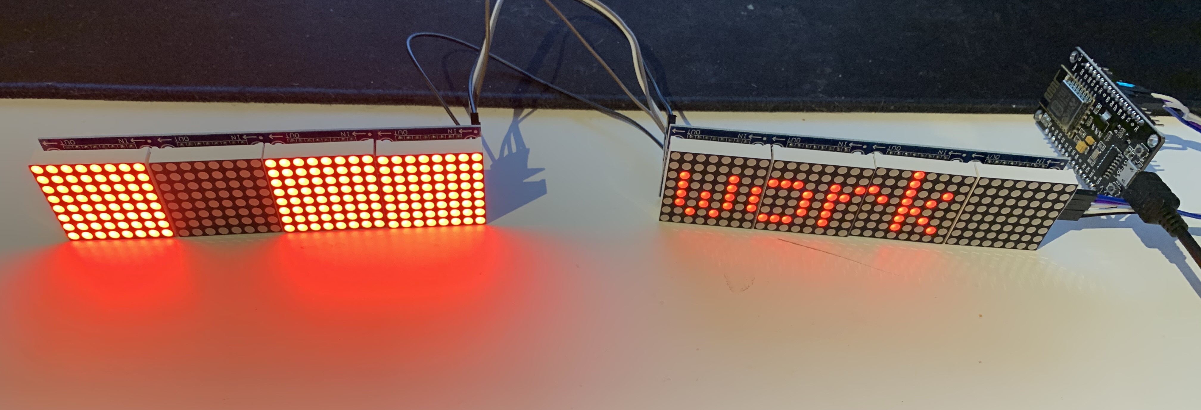
in the meantime i have 4 max7129 modules, because i wanted to be sure, if they have to be compatible with each other, after all, you often have to run them with a different config. Now it still doesn't work, although I have 2 modules from the same seller and simply put them in series. Of course I paid as much attention as possible to the solder connection, but it still doesn't work. The second matrix glows completely sometimes and sometimes only with a few blocks. Does anyone have a tip? I'm running on the 3 Volt voltage. With the 5 V voltage both modules flicker completely. Here is my code:
#include <ESP8266WiFi.h>
#include <SPI.h>
#include <ESP8266HTTPClient.h>
#include <MD_Parola.h>
#include <MD_MAX72xx.h>
#include <ArduinoOTA.h>

#define MAX_DEVICES 8
#define HARDWARE_TYPE MD_MAX72XX::FC16_HW
#define CLK_PIN   D5 // or SCK
#define DATA_PIN  D7 // or MOSI
#define CS_PIN    D3 // or SS

const char* ssid = "XXX";
const char* password = "XXX";
const char* apiHost = "http://XXXX";

uint8_t degC[] = {5, 6 , 15 , 9 , 15 , 6 };

//MESSAGE
textEffect_t scrollEffect = PA_SCROLL_LEFT;
uint8_t frameDelay = 60;
uint8_t messagePause = 100;
char curMessage[300]   = "Smart Notification";
MD_Parola Parola = MD_Parola(HARDWARE_TYPE, CS_PIN, MAX_DEVICES);

void setup() {
  Serial.begin(115200);
  Serial.println("Setup");

  Parola.begin();
  Parola.addChar('
Parola.displayClear();
Parola.displaySuspend(false);
Parola.setIntensity(1); // Values from 0 to 15
scrollEffect = (PA_SCROLL_LEFT);
Parola.setTextEffect(scrollEffect, scrollEffect);
Parola.setPause(messagePause);
WiFi.begin(ssid, password);
while (WiFi.status() != WL_CONNECTED) {
Serial.println("Error connection to Wifi");
delay(500);
}
Serial.print("Connected: "); Serial.println(WiFi.localIP());
String successMessage = "Successfully connected to Wifi Network";
successMessage.toCharArray(curMessage, sizeof(curMessage));
ArduinoOTA.begin();
}
void loop() {
ArduinoOTA.handle();
if (Parola.displayAnimate()) {
Parola.displayScroll(curMessage, PA_LEFT, scrollEffect, frameDelay);
Serial.println("Text displayed");
getApiData();
}
}
void getApiData() {
WiFiClient client;
HTTPClient http;
Serial.print("[HTTP] begin...\n");
if (http.begin(client, apiHost)) {
Serial.print("[HTTP] GET...\n");
int httpCode = http.GET();

if (httpCode > 0) {
  Serial.printf("[HTTP] GET... code: %d\n", httpCode);

  if (httpCode == HTTP_CODE_OK || httpCode == HTTP_CODE_MOVED_PERMANENTLY) {
    String payload = http.getString();
    Serial.println(payload);
    payload.toCharArray(curMessage, sizeof(curMessage));
  }
} else {
  Serial.printf("[HTTP] GET... failed, error: %s\n", http.errorToString(httpCode).c_str());
}

http.end();
} else {
Serial.printf("[HTTP} Unable to connect\n");
}
}
