That is the technical justification however isn't a reasonable one once you realize the 16MHz clock speed of the Arduino. My math is more like, 16MHz / 1bit = 16MHz...
I want to simulate a buck converter like the chip LM2576. It looks like the LM2576 has a frequency of 52kHz so 62kHz will do after all!
Why not? If you start to divide 16MHz down you're in the KHz range pretty fast. And you still need a tick per step (/ resolution) and the system clock at 16MHz is the fastest the Arduino (uno-ish) has (it has no PLL). You can run the Arduino at 20MHz but then you have to check if all libraries and HAL can handle the switch to 20MHz.
You have to choose one of the timer PWM modes that counts to less than 255. However you get less
(duty-cycle) resolution at higher frequencies. The datasheet has all the gory details, timer0 and
timer2 are slightly different, note, and timer1 is 16 bit with more modes.
If you configure timer1 (ATmega328P as in Uno etc.) to use fast PWM ( Wave Generation Mode 14) you can get up to 8 MHz for a 16MHz clock if the timer is set to directly manipulate a pin dedicated to it, in this case OC1A (pin D9):
  //set timer1 toggle at xHz
  TCCR1A = 0;// set entire TCCR1A register to 0
  TCCR1B = 0;// same for TCCR1B
  TCNT1  = 0;//initialize counter value to 0

  ICR1 = 1 ;      // set TOP
  OCR1A = 0 ;   // set duty cycle

  TCCR1A |= ( 1 << COM1A1 ) | (1 << WGM11) ;

  // wg mode 14
  TCCR1B |= (1 << WGM12) | (1 << WGM13);
  // prescaler  1
  TCCR1B |= (1 << CS10)  ;
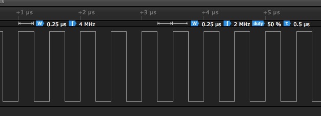
The resolution is poor though close to the clock frequency
You get 8 MHz, then 5.33..MHz , then 4 MHz then 3.2 MHz then 2.66.. MHz etc.