MCP1640 boost regulator outputting 8 volts?!

thegoodhen:
Haha, thanks! Yea, works now. Seems like I overengineered it quite a bit, too. It's a clock-and I've done so far with energy saving that the batteries will die due to their shelf-life sooner then they will completely discharge. :smiley: The estimated battery life, self-discharge included is ~25 years. Oh well. :smiley:

I like to say that anything worth doing is worth over-doing! Sounds interesting, how about a brief summary of the project? 25 years, you must be kidding :smiley:

Nah! :smiley: It's a clock project for my mum (or other people in need).
My mum is slightly visually impaired-she can't use normal clock and has to resort to her blind-friendly watch. However, she also has carpal syndrome and loses touch in her hand every once in a while, making it impossible for her to use it. Additionally, it's an old russian watch-and you know what they say about those. Russian watches are the best-they are the fastest.

(To be fair it's now about 30 years old and still going strong.)

Talking watch would be an option, but its annoying sound (for other people too), (presumably short battery life, I don't know) and price for a new piece make it a bit inconvenient.

I have thus decided to build her a clock she can use.
It blinks out a specific sequence in 3 colors. While she cannot really see small things, it is easy for her to tell the colors apart one another. This sequence is similar to roman numerals. 10s have a blue color, 5s have a green one and 1s have a red color. (To be user selectable in future).

for instance, 15:20 would be XV:XX in roman numerals. Here it is BLUE blink, GREEN blink (pause) BLUE blink BLUE blink.

The clock wakes up on interrupt and then goes to deep sleep mode. internal pullups are used, this being (presumably) the reason for slightly higher power consumption than estimated. Other reason could be the DMM inaccuracy. Even when a bit worse than expected, it takes about 4uA. When it powers up, it takes just about 5ma-the LEDs are pretty bright already at this level. If used once every hour, even at night, it will last about 25 years on 2xAA (which is a theoretical value, their shelf life doesn't allow for that).
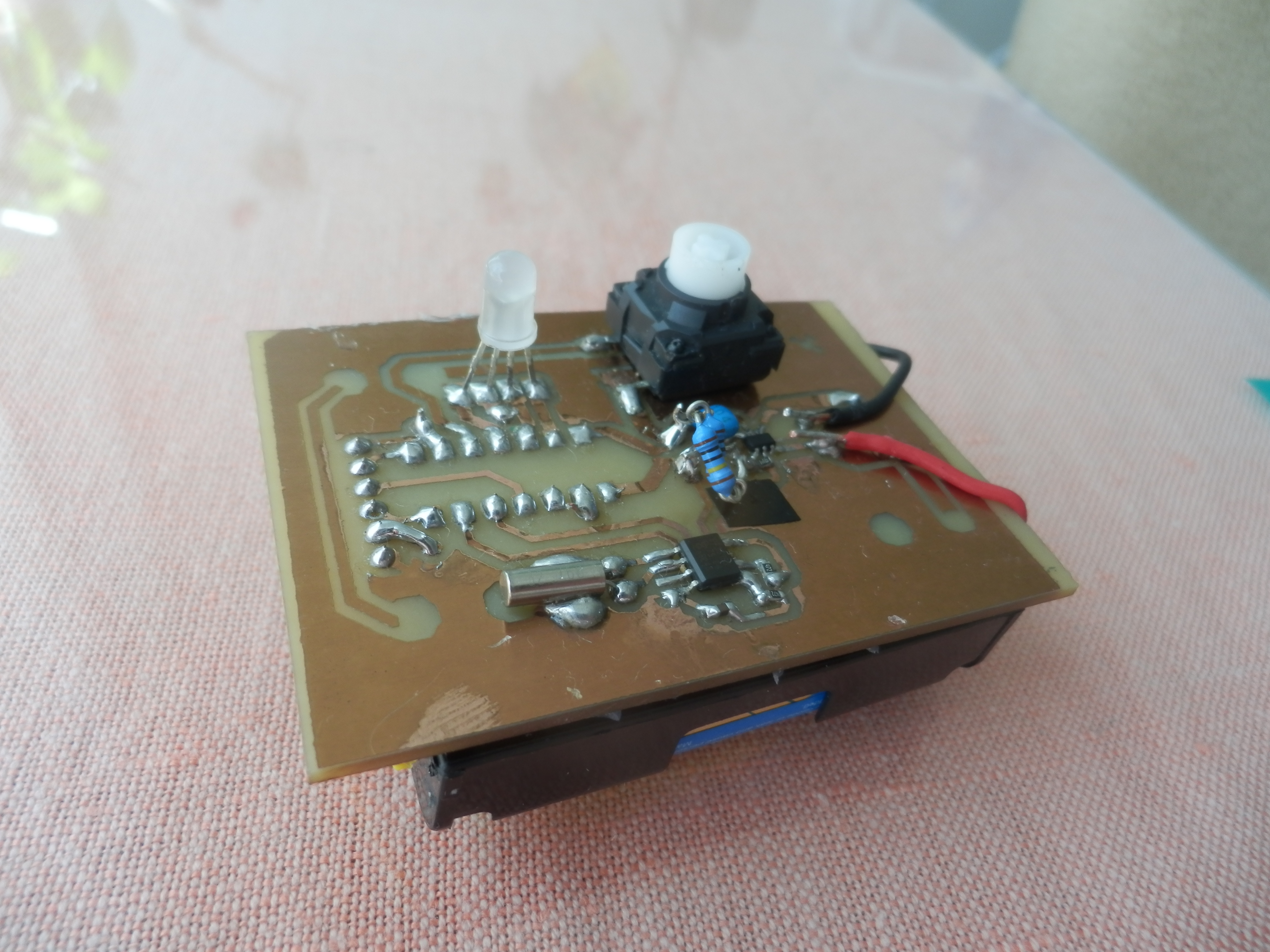
Photos:

Remarks: Yea, that's a fingerprint. I didn't wash off the photoresist, because I like how it looks. Then I touched it with alcohol on my hoof.

Yea, the button is humongous. Couldn't find the one I've designed it for. It's supposed to be something like this:
http://static2.tme.eu/katalog_pics/b/5/a/b5a8fd5059671d5d753a73c6a25fb128/tact-24k-f.jpg

The bulged resistors are supposed to be one smd resistor, but I didn't have one.
The 2 wires (black and red) are not supposed to be here; it's designed for THT battery holders; again, I didn't have those.

The bypass capacitor is a bit far away from the clock chip; whatever-in the datasheet, it doesn't even mention you should put a bypass cap there (AFAIK) . I guess it has such a low current draw the stray capacitance is enough.

The 2 jumper wires on the other side are not necessary; they were added as an afterthought. Will remove those in next revision.

I am planning to get a thin piece of something (cardboard, plastic?) laser cut. It will have holes for the LED and the button and will protect the smds. It will be glued on the upper side of the board.

This is the 3rd prototype of this device; I think it's pretty much ready for larger production-would be interesting to target this niche market with something like this-it's very cheap to do, even with the work, I could sell it for ~$10-20.

I have done 2 similar devices. One is this one http://www.instructables.com/id/Schematics-n-stuff/
(bit of a proof of concept, pretty old too)

And one is the aforementioned clock with 36 leds.

Hi, I like the concept and the way you have approached it, good what you can get prototypes too, nothing flash just get the job done.
Great proof of concept and I wouldn't worry about over engineering, if its going to be handled a lot, that may be in its favour.
Great idea.
Good luck mate.

Tom....... :slight_smile:

Wow, good concept, nice project, obviously a lot of effort over some time. Thanks for sharing. Hadn't heard the line about the best watches being the fastest, haha!

TomGeorge:
Hi, I like the concept and the way you have approached it, good what you can get prototypes too, nothing flash just get the job done.
Great proof of concept and I wouldn't worry about over engineering, if its going to be handled a lot, that may be in its favour.
Great idea.
Good luck mate.

Tom....... :slight_smile:

Thanks. You are right! Seems like I've even found the right batteries for it. Energizer L91-FR6 have 3000maHs and ~15 years shelf life.

No problems, thanks. Yea, I've made the first proof of concept about 3 or 4 years ago-that was without an RTC-that thing was running on an internal oscillator-I needed to manually compensate for the drift. I had this mechanism there that would round the time to the closest half hour when you held the button for a bit longer. :smiley:
I am thinking about building a blind friendly binary clock next. Something like this:


Only instead of the leds several buttons and a vibration motor. Once you press the button, it either vibrates (1) or doesn't (0). Might be used even by severely visually impaired people and it would have a fast readout and would be nice overall.

(Other than that, I am also working on a walking robot and several other things.)

Thanks for all the support! Really appreciate it.

Edit: as to this project: I will add custom color selection, readout speed adjustment and automatic ambient aware brightness correction (or how it's called). I'll just use the leds that are there, they are wired between 2 pins of the micro; they can be reverse biased and the capacity can be measured to obtain the ambient brightness info.

So it has been working a treat, no problems whatsoever. Now I have tried to measure the battery voltage using a multimeter. It froze and I can't get it to work again. The built-in debug shows RTC communication error. Then it freezes. I have no idea what the hay is going on. .-.

thegoodhen:
So it has been working a treat, no problems whatsoever. Now I have tried to measure the battery voltage using a multimeter. It froze and I can't get it to work again. The built-in debug shows RTC communication error. Then it freezes. I have no idea what the hay is going on. .-.

Using the multimeter caused this? :fearful:

Yea, but no worries. I was probing it using a scope and it fixed it. Apparently nothing to worry about... Or is there.