I'm attempting to use the MCP4161-103 digital potentiometer with an Arduino microcontroller. I'm using the 10k Ohm version with 8-bit precision (256 resistor steps), with an Arduino Uno R3, and Arduino IDE v2.3.4.
I'm attempting to communicate with the potentiometer chip via SPI, and I'm running into difficulties expected voltage and resitance values from the wiper pin on the digipot.
My wiring:
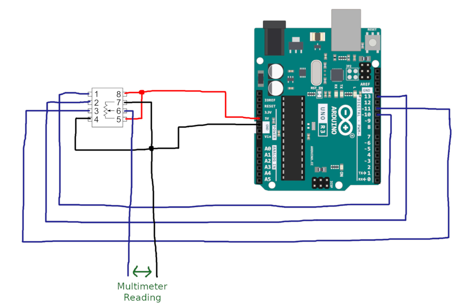

As far as I understand, the two SPI pins on the MCP4161 (SDI & SDO) have been multiplexed into a single pin for both MOSI and MISO equivalents on the Arduino. So, if the user desires to have two-way communication, a pull-up resistor is needed on either MISO or MOSI, as shown in this example with an older version of the chip. However, in my case I do not have a need to read from the potentiometer, so I left MISO disconnected. I only want to set the resistance wiper value.
However, I'm unable to read the expected voltage or resistance figures from the wiper P0W pin on the pot.
Reading the voltage on the P0W wiper pin on a multimeter, with respect to the Arduino's ground, always results in either a floating reading of near 0V, or a somewhat stable reading of 2.5V (it appears to be the latter only if I connect the wiper pins P0A and P0B, to 5V and GND respectivelly, after I power the Arduino). What I'm expecting to see when doing that reading is something simillar to the following:

I also cannot read any resistance measurement between the P0W wiper pin and either the P0A or P0B pins. With a normal analog potentiometer, it is possible to read the currently selected resistance value using a multimeter by measuring resistance between the wiper pin and either the power or ground pins. With this digitpot, I can only read the maximum resistance of 10k Ohm if I read between P0A and P0B, but no resistance readings show up through the P0W pin, no matter the configuration or power state.
From the datasheet of the MCP4161, it appears that the digipot initializes it's wiper value at the halfway point every time it's powered on, so the 2.5V value makes sense to appear initially after powerup.

However, the voltage on the wiper pin does not effectively change if I try to change the wiper position using any of the example code I could find for the MCP4161 or simillar digipots.
I have tried using the following code examples;
From RobTillaart's Arduino library:
#include "MCP4261.h"

uint32_t start, stop;

//  select, shutdown, dataIn, dataOut, clock == SOFTWARE SPI
MCP4161 pot(10, 6, 12, 11, 13);

//  select, shutdown, &SPI === HW SPI UNO clock = 13, dataOut = 11
//MCP4161 pot(10, 6, &SPI);

void setup()
{
  Serial.begin(9600);
  Serial.println(__FILE__);

  SPI.begin();

  pot.begin();

  Serial.println("\nDone...");
}

void loop()
{
  test_extremes();
}

void test_extremes()
{
  Serial.println(__FUNCTION__);
  delay(10);

  Serial.println("0");
  pot.setValue(0, 0);
  delay(2000);

  Serial.println(MCP42XX_MIDDLE_VALUE);
  pot.setValue(0, MCP42XX_MIDDLE_VALUE);
  delay(2000);

  Serial.println(MCP42XX_MAX_VALUE);
  pot.setValue(0, MCP42XX_MAX_VALUE);
  delay(2000);
}
From Instructables tutorial:
#include <MCP4131.h>

const int chipSelect = 10;
unsigned int wiperValue;
int i;

// Create MCP4131 object nominating digital pin used for Chip Select
MCP4131 Potentiometer(chipSelect);

void setup() {
  // Reset wiper position to 0 Ohms
  wiperValue = 0;
  Potentiometer.writeWiper(wiperValue);

  // Begin Serial port and print out welcome message
  Serial.begin(9600);
  Serial.println("MCP4131 Digital Potentiometer Test");

}

void loop() {
  // Starting at 0 Ohms increment MCP4131 up to max resistance
  for ( i = 0 ; i <= 128; i++){
    Potentiometer.incrementWiper();
    delay(100);
  }

  // Print out message showing voltage is turning
  Serial.println("5V turning point");

  // Starting at max resistance decrement MCP4131 to 0 Ohms
  for ( i = 128 ; i >= 0; i--){
    Potentiometer.decrementWiper();
    delay(100);
  }

  // Print out message showing voltage is turning
  Serial.println("0V turning point");
}
From the following Arduino Forums posting:
#include <SPI.h>
//Defined SPI pins
#define MOSI 11
#define MISO 12
#define SCK 13
#define CS 10

void setup() {
  Serial.begin(9600);

  //Define SPI IOs
  pinMode(MOSI, OUTPUT); //SDI
  pinMode(MISO, INPUT);  //SDO
  pinMode(SCK, OUTPUT);
  pinMode(CS, OUTPUT);

  //Initialise SPI interface
  //SPI clock speed:10MHz, Data Shift:MSB First, Data Clock Idle: SPI_MODE0 (MODE =00)
  SPI.beginTransaction(SPISettings(10000000,MSBFIRST,SPI_MODE0));
  SPI.begin();

  Serial.println("COM Ready");
}

void loop(){
uint8_t in;
  for(int i=0; i<256;++i){
        digitalWrite(CS,LOW);
	in = SPI.transfer(i)
	Serial.print(i,DEC);
        Serial.print(": ");
        Serial.println(in,DEC);
        digitalWrite(CS,HIGH);
	delay(1000);
  }
}
And a few more I could find online.
All of the above use SPI mode 0, which the chip's datasheet mentions is a valid SPI mode for the chip. None of the code examples I tried result in any visible change in the voltage of resistance readings on the wiper pin of the digipot.
I have also tried connecting the wiper pin to 5V across a 100k Ohm resistor, as well as connecting the MISO line from Arduino's pin 12 to the SDI/SDO pin on the pit via 100 Ohm resistor, as suggested by some other tutorials. I've also tried this with several MCP4161 chips, and with a different microcontroller, all to no avail.
What exactly am I doing wrong here? How am I supposed to connect this digital potentiometer chip in order to get the expected voltage or resistance readings from the digipot's wiper pin?
Thanks for reading my post, any guidance is appreciated.

