You should be able to follow the wiring from this photo as you can zoom in close.
Yellow is MOSI
White is MISO
Green is SCK
Blue is SS or CS
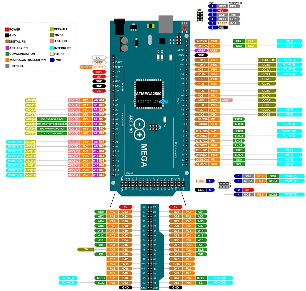
There is a bit of a perspective issue with the wires plugged into the Mega. It looks like they are plugged into pin 48. But they are not. I used pins 50-53 as per this.
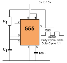
100nF decoupling cap across the 555 pins 1 and 8.
10nF cap on 555 pin 5
12nF cap on 555 pin 3 - that is actually in the wrong spot, should be pin 2 or 6 which are connected.
But that wiring error is irrelevant for the moment because I am using my multimeter to measure the resistance across digital POT pins PA0 and PW0, PB0 and pW0, PA1 and PW1, PB1 and PW1.
And I am not succeeding in changing any resistances.
#include "MCP4XXXXPOT.h"
#include "debug.h"


CMCP42010 mcp41xxxDigitPot(53, 255, 255);
#define CHANNEL 0


void setResistance(const uint16_t nResistance)
{
  Serial.print(F("Setting resistance to "));
  Serial.print(nResistance);
  Serial.println(F(" ohms..."));
  mcp41xxxDigitPot.setOhm(CHANNEL, nResistance);
  Serial.print(F("Calculated frequency "));
  double dFrequency = 0.72 / (nResistance * (6.8 / 1000000000));
  if (dFrequency > 1000.0)
  {
    Serial.print(dFrequency / 1000.0);
    Serial.println(F("kHz"));
  }
  else
  {
    Serial.print(dFrequency);
    Serial.println(F("Hz"));
  }
}

void setup()
{
  Serial.begin(115200);
  while (!Serial);
  mcp41xxxDigitPot.begin(RES_AW, 0);
  //setResistance(MCP_POT_MAX_VALUE);
  Serial.println(F("Setup complete!"));
}

void loop()
{
  if (Serial.available())
  {
    uint16_t nResistanceOhms = Serial.parseInt();
    setResistance(nResistanceOhms);
  }
}
MCP4XXXXPOT.cpp
#line 2 "MCP4XXXXPOT.cpp"
#include "MCP4XXXXPOT.h"

//  see page 18 datasheet
#define MCP42XXX_IGNORE_CMD        0x00
#define MCP42XXX_WRITE_CMD         0x10
#define MCP42XXX_SHUTDOWN_CMD      0x20
#define MCP42XXX_NONE_CMD          0x30


  //       HARDWARE SPI
CMCP42XXX::CMCP42XXX(const uint8_t nSSPin, const uint8_t nResetPin, const uint8_t nShutDownPin, const __SPI_CLASS__ *pSPI)
{
  m_nNumChannels = 2;
  m_nSSPin = nSSPin;
  m_nResetPin = nResetPin;
  m_nShutDownPin = nShutDownPin;
  m_nMOSIPin = 255;
  m_nSCKPin = 255;
  m_bIsHWSPI = true;
  m_pSPI = m_pSPI;
}

//       SOFTWARE SPI
CMCP42XXX::CMCP42XXX(const uint8_t nSSPin, const uint8_t nResetPin, const uint8_t nShutDownPin, const uint8_t nMOSIPin, const uint8_t nSCKPin)
{
  m_nNumChannels = 2;
  m_nSSPin = nSSPin;
  m_nResetPin = nResetPin;
  m_nShutDownPin = nShutDownPin;
  m_nMOSIPin = nMOSIPin;
  m_nSCKPin = nSCKPin;
  m_bIsHWSPI = false;
  m_pSPI = NULL;
}

void CMCP42XXX::begin(const enum_pot_use_type eUseType, const uint8_t nValue)
{
  m_eUseType = eUseType;

  pinMode(m_nSSPin, OUTPUT);
  digitalWrite(m_nSSPin, HIGH);
  pinMode(m_nResetPin, OUTPUT);
  digitalWrite(m_nResetPin, HIGH);
  pinMode(m_nShutDownPin, OUTPUT);
  digitalWrite(m_nShutDownPin, HIGH);

  setSPIspeed(1000000);

  if (m_bIsHWSPI)
  {
    m_pSPI->end();
    m_pSPI->begin();
    delay(1);
  }
  else
  {
    pinMode(m_nMOSIPin, OUTPUT);
    pinMode(m_nSCKPin,   OUTPUT);
    digitalWrite(m_nMOSIPin, LOW);
    digitalWrite(m_nSCKPin,   LOW);
  }
  reset(nValue);
}

void CMCP42XXX::reset(const uint8_t nValue)
{
  digitalWrite(m_nResetPin, LOW);
  digitalWrite(m_nResetPin, HIGH);
  setValue(nValue);  //  set all to same nValue.
}


/////////////////////////////////////////////////////////////////////////////
//
//  SET VALUE
//
bool CMCP42XXX::setValue(uint8_t nValue)
{
  if (m_eUseType == RES_AW)
  {
    nValue = MCP_POT_MAX_VALUE - nValue;
  }
  m_arrayChannels[0] = nValue;
  m_arrayChannels[1] = nValue;
  updateDevice(2, nValue, MCP42XXX_WRITE_CMD);
  return true;
}


bool CMCP42XXX::setValue(const uint8_t nChannel, uint8_t nValue)
{
  if (nChannel >= m_nNumChannels)
    return false;
  if (m_eUseType == RES_AW)
  {
    nValue = MCP_POT_MAX_VALUE - nValue;
  }
  m_arrayChannels[nChannel] = nValue;
  m_arrayChannels[nChannel] = nValue;
  updateDevice(nChannel, nValue, MCP42XXX_WRITE_CMD);
  return true;
}


uint8_t CMCP42XXX::getValue(const uint8_t nChannel)
{
  if (nChannel >= m_nNumChannels)
    return 0;
  return m_arrayChannels[nChannel];
}


/////////////////////////////////////////////////////////////////////////////
//
//  OHM - wrappers
//
void CMCP42XXX::setMaxOhm(const uint32_t nMaxOhms)
{
  m_nMaxOhm = nMaxOhms;
}

uint32_t CMCP42XXX::getMaxOhm()
{
  return m_nMaxOhm;
}

void CMCP42XXX::setOhm(const uint8_t nChannel, uint32_t nOhms)
{
  if (m_eUseType == RES_AW)
    nOhms = getMaxOhm() - nOhms;
  setValue(nChannel, round(nOhms * 255.0 / m_nMaxOhm));
}

uint32_t CMCP42XXX::getOhm(const uint8_t nChannel)
{
  return round(getValue(nChannel) * (m_nMaxOhm / 255.0));
}


/////////////////////////////////////////////////////////////////////////////
//
//  OTHER
//
uint8_t CMCP42XXX::pmCount()
{
  return m_nNumChannels;
}


void CMCP42XXX::powerOn()
{
  digitalWrite(m_nShutDownPin, HIGH);
}


void CMCP42XXX::powerOff()
{
  digitalWrite(m_nShutDownPin, LOW);
}


bool CMCP42XXX::isPowerOn()
{
  return digitalRead(m_nShutDownPin) == HIGH;
}


/////////////////////////////////////////////////////////////////////////////
//
//  SPI
//
void CMCP42XXX::setSPIspeed(const uint32_t nSpeed)
{
  m_nSPISpeed = nSpeed;
  _spi_settings = SPISettings(m_nSPISpeed, MSBFIRST, SPI_MODE0);
}


uint32_t CMCP42XXX::getSPIspeed()
{
  return m_nSPISpeed;
}


void CMCP42XXX::setSWSPIDelay(const uint16_t nDelay)
{
  m_nSPIDelay = nDelay;
}


uint16_t CMCP42XXX::getSWSPIdelay()
{
  return m_nSPIDelay;
}


bool CMCP42XXX::usesHWSPI()
{
  return m_bIsHWSPI;
}


/////////////////////////////////////////////////////////////////////////////
//
//  PROTECTED
//
void CMCP42XXX::updateDevice(const uint8_t nChannel, const uint8_t nValue, const uint8_t nCommand)
{
  uint8_t nTempCommand = nCommand;
  if (nChannel == 0)
    nTempCommand |= 1;   //  01
  if (nChannel == 1)
    nTempCommand |= 2;   //  10
  if (nChannel == 2)
    nTempCommand |= 3;   //  11 => both potentiometers
  //  otherwise ignore
  digitalWrite(m_nSSPin, LOW);
  if (m_bIsHWSPI)
  {
    m_pSPI->beginTransaction(_spi_settings);
    m_pSPI->transfer(nTempCommand);
    m_pSPI->transfer(nValue);
    m_pSPI->endTransaction();
  }
  else      //  Software SPI
  {
    swSPI_transfer(nTempCommand);
    swSPI_transfer(nValue);
  }
  digitalWrite(m_nSSPin, HIGH);
}


//  MSBFIRST
void  CMCP42XXX::swSPI_transfer(const uint8_t nVal)
{
  //  split m_nSPIDelay in equal dLow and dHigh
  //  dLow should be longer one when m_nSPIDelay = odd.
  uint16_t dHigh = m_nSPIDelay / 2;
  uint16_t dLow  = m_nSPIDelay - dHigh;

  uint8_t nSCKPin = m_nSCKPin;
  uint8_t nMOSIPin = m_nMOSIPin;
  //  MSBFIRST
  for (uint8_t mask = 0x80; mask; mask >>= 1)
  {
    digitalWrite(nMOSIPin,(nVal & mask));
    digitalWrite(nSCKPin, HIGH);
    if (dHigh > 0)
      delayMicroseconds(dHigh);
    digitalWrite(nSCKPin, LOW);
    if (dLow > 0)
      delayMicroseconds(dLow);
  }
}


////////////////////////////////////////////////////////////////////////////
//
//  DERIVED CLASSES MCP41000 SERIES
//
CMCP41010::CMCP41010(const uint8_t nSSPin, const uint8_t nResetPin, const uint8_t nShutDownPin, const __SPI_CLASS__ *pSPI)
        :CMCP42XXX(nSSPin, nResetPin, nShutDownPin, pSPI)
{
  m_nNumChannels = 1;
  m_nMaxOhm  = 10000;
}

CMCP41010::CMCP41010(const uint8_t nSSPin, const uint8_t nResetPin, const uint8_t nShutDownPin, const uint8_t nMOSIPin, const uint8_t nSCKPin)
        :CMCP42XXX(nSSPin, nResetPin, nShutDownPin, nMOSIPin, nSCKPin)
{
  m_nNumChannels = 1;
  m_nMaxOhm  = 10000;
}

CMCP41050::CMCP41050(const uint8_t nSSPin, const uint8_t nResetPin, const uint8_t nShutDownPin, const __SPI_CLASS__ *pSPI)
        :CMCP42XXX(nSSPin, nResetPin, nShutDownPin, pSPI)
{
  m_nNumChannels = 1;
  m_nMaxOhm  = 50000;
}

CMCP41050::CMCP41050(const uint8_t nSSPin, const uint8_t nResetPin, const uint8_t nShutDownPin, const uint8_t nMOSIPin, const uint8_t nSCKPin)
        :CMCP42XXX(nSSPin, nResetPin, nShutDownPin, nMOSIPin, nSCKPin)
{
  m_nNumChannels = 1;
  m_nMaxOhm  = 10000;
}

CMCP41100::CMCP41100(const uint8_t nSSPin, const uint8_t nResetPin, const uint8_t nShutDownPin, const __SPI_CLASS__ *pSPI)
        :CMCP42XXX(nSSPin, nResetPin, nShutDownPin, pSPI)
{
  m_nNumChannels = 1;
  m_nMaxOhm  = 100000;
}

CMCP41100::CMCP41100(const uint8_t nSSPin, const uint8_t nResetPin, const uint8_t nShutDownPin, const uint8_t nMOSIPin, const uint8_t nSCKPin)
        :CMCP42XXX(nSSPin, nResetPin, nShutDownPin, nMOSIPin, nSCKPin)
{
  m_nNumChannels = 1;
  m_nMaxOhm  = 100000;
}


////////////////////////////////////////////////////////////////////////////
//
//  DERIVED CLASSES MCP42000 SERIES
//
CMCP42010::CMCP42010(const uint8_t nSSPin, const uint8_t nResetPin, const uint8_t nShutDownPin, const __SPI_CLASS__ *pSPI)
        :CMCP42XXX(nSSPin, nResetPin, nShutDownPin, pSPI)
{
  m_nNumChannels = 2;
  m_nMaxOhm  = 10000;
}

CMCP42010::CMCP42010(const uint8_t nSSPin, const uint8_t nResetPin, const uint8_t nShutDownPin, const uint8_t nMOSIPin, const uint8_t nSCKPin)
        :CMCP42XXX(nSSPin, nResetPin, nShutDownPin, nMOSIPin, nSCKPin)
{
  m_nNumChannels = 2;
  m_nMaxOhm  = 10000;
}

CMCP42050::CMCP42050(const uint8_t nSSPin, const uint8_t nResetPin, const uint8_t nShutDownPin, const __SPI_CLASS__ *pSPI)
        :CMCP42XXX(nSSPin, nResetPin, nShutDownPin, pSPI)
{
  m_nNumChannels = 2;
  m_nMaxOhm  = 50000;
}

CMCP42050::CMCP42050(const uint8_t nSSPin, const uint8_t nResetPin, const uint8_t nShutDownPin, const uint8_t nMOSIPin, const uint8_t nSCKPin)
        :CMCP42XXX(nSSPin, nResetPin, nShutDownPin, nMOSIPin, nSCKPin)
{
  m_nNumChannels = 2;
  m_nMaxOhm  = 50000;
}

CMCP42100::CMCP42100(const uint8_t nSSPin, const uint8_t nResetPin, const uint8_t nShutDownPin, const __SPI_CLASS__ *pSPI)
        :CMCP42XXX(nSSPin, nResetPin, nShutDownPin, pSPI)
{
  m_nNumChannels = 2;
  m_nMaxOhm  = 100000;
}

CMCP42100::CMCP42100(const uint8_t nSSPin, const uint8_t nResetPin, const uint8_t nShutDownPin, const uint8_t nMOSIPin, const uint8_t nSCKPin)
        :CMCP42XXX(nSSPin, nResetPin, nShutDownPin, nMOSIPin, nSCKPin)
{
  m_nNumChannels = 2;
  m_nMaxOhm  = 100000;
}
MCP4XXXXPOT.h
#line 2 "MCP4XXXXPOT.h"
#pragma once

#include "Arduino.h"
#include "SPI.h"


#ifndef MCP_POT_MIDDLE_VALUE
#define MCP_POT_MIDDLE_VALUE          128
#endif

#ifndef MCP_POT_MAX_VALUE
#define MCP_POT_MAX_VALUE             255
#endif


#ifndef __SPI_CLASS__
  //  MBED must be tested before RP2040
  #if defined(ARDUINO_ARCH_MBED)
  #define __SPI_CLASS__   SPIClass
  #elif defined(ARDUINO_ARCH_RP2040)
  #define __SPI_CLASS__   SPIClassRP2040
  #else
  #define __SPI_CLASS__   SPIClass
  #endif
#endif


typedef enum{POT_AWB, RES_AW, RES_WB} enum_pot_use_type;


class CMCP42XXX
{
  public:
    //       HARDWARE SPI
    CMCP42XXX(const uint8_t nSPin, const uint8_t nResetPin, const uint8_t nShutDownPin, const __SPI_CLASS__ *pSPI = (__SPI_CLASS__*)&SPI);
    //       SOFTWARE SPI
    CMCP42XXX(const uint8_t nSSPin, const uint8_t nResetPin, const uint8_t nShutDownPin, const uint8_t nMOSIPin, const uint8_t nSCKPin);

    void     begin(const enum_pot_use_type eUseType, uint8_t nValue = MCP_POT_MIDDLE_VALUE);
    void     reset(uint8_t nValue = MCP_POT_MIDDLE_VALUE);

    //       set both potmeters to the same value
    bool     setValue(uint8_t nValue);
    //       set single potmeter, pm = 0 or 1
    bool     setValue(uint8_t nChannel, const uint8_t nValue);
    uint8_t  getValue(const uint8_t nChannel = 0);

    //  EXPERIMENTAL
    //  Ohm wrappers
    void     setMaxOhm(const uint32_t nOhms);
    uint32_t getMaxOhm();
    void     setOhm(const uint8_t nChannel, uint32_t nResistanceOhms);
    uint32_t getOhm(const uint8_t nChannel);


    //       speed in Hz
    void     setSPIspeed(uint32_t speed);
    uint32_t getSPIspeed();
    void     setSWSPIDelay(uint16_t del = 0);
    uint16_t getSWSPIdelay();

    //       MISC
    uint8_t  pmCount();
    void     powerOn();
    void     powerOff();
    bool     isPowerOn();

    //       debugging
    bool     usesHWSPI();


  protected:
    enum_pot_use_type m_eUseType;
    uint8_t  m_nMOSIPin;
    uint8_t  m_nSCKPin;
    uint8_t  m_nSSPin;
    uint8_t  m_nResetPin;
    uint8_t  m_nShutDownPin;

    uint8_t  m_arrayChannels[2];
    uint8_t  m_nNumChannels;
    uint32_t m_nMaxOhm;

    void     updateDevice(const uint8_t nChannel, const uint8_t nValue, const uint8_t nCommand);
    void     swSPI_transfer(uint8_t value);

    bool     m_bIsHWSPI;
    uint16_t m_nSPIDelay = 0;
    uint32_t m_nSPISpeed;
    __SPI_CLASS__ *m_pSPI;
    SPISettings     _spi_settings;
};


/////////////////////////////////////////////////////////////////////////////
//
//  DERIVED CLASSES CMCP41000 SERIES
//
class CMCP41010 : public CMCP42XXX
{
  public:
    CMCP41010(const uint8_t nSSPin, const uint8_t nResetPin, const uint8_t nShutDownPin, const __SPI_CLASS__ *pSPI = (__SPI_CLASS__*)&SPI);
    CMCP41010(const uint8_t nSSPin, const uint8_t nResetPin, const uint8_t nShutDownPin, const uint8_t nMOSIPin, const uint8_t nSCKPin);
};


class CMCP41050 : public CMCP42XXX
{
  public:
    CMCP41050(const uint8_t nSSPin, const uint8_t nResetPin, const uint8_t nShutDownPin, const __SPI_CLASS__ *pSPI = (__SPI_CLASS__*)&SPI);
    CMCP41050(const uint8_t nSSPin, const uint8_t nResetPin, const uint8_t nShutDownPin, const uint8_t nMOSIPin, const uint8_t nSCKPpin);
};


class CMCP41100 : public CMCP42XXX
{
  public:
    CMCP41100(const uint8_t nSSPin, const uint8_t nResetPin, const uint8_t nShutDownPin, const __SPI_CLASS__ *pSPI = (__SPI_CLASS__*)&SPI);
    CMCP41100(const uint8_t nSSPin, const uint8_t nResetPin, const uint8_t nShutDownPin, const uint8_t nMOSIPin, const uint8_t nSCKPpin);
};


/////////////////////////////////////////////////////////////////////////////
//
//  DERIVED CLASSES CMCP42000 SERIES
//
class CMCP42010 : public CMCP42XXX
{
  public:
    CMCP42010(const uint8_t nSSPin, const uint8_t nResetPin, const uint8_t nShutDownPin, const __SPI_CLASS__ *pSPI = (__SPI_CLASS__*)&SPI);
    CMCP42010(const uint8_t nSSPin, const uint8_t nResetPin, const uint8_t nShutDownPin, const uint8_t nMOSIPin, const uint8_t nSCKPpin);
};


class CMCP42050 : public CMCP42XXX
{
  public:
    CMCP42050(const uint8_t nSSPin, const uint8_t nResetPin, const uint8_t nShutDownPin, const __SPI_CLASS__ *pSPI = (__SPI_CLASS__*)&SPI);
    CMCP42050(const uint8_t nSSPin, const uint8_t nResetPin, const uint8_t nShutDownPin, const uint8_t nMOSIPin, const uint8_t nSCKPpin);
};


class CMCP42100 : public CMCP42XXX
{
  public:
    CMCP42100(const uint8_t nSSPin, const uint8_t nResetPin, const uint8_t nShutDownPin, const __SPI_CLASS__ *pSPI = (__SPI_CLASS__*)&SPI);
    CMCP42100(const uint8_t nSSPin, const uint8_t nResetPin, const uint8_t nShutDownPin, const uint8_t nMOSIPin, const uint8_t nSCKPpin);
};