Currently, I work on nano 33 BLE Sense, I have a project with 3-phase motor control, first step I need to measure the current sensor and get the waveform in real-time, I got a reference to access ADC on Nano 33 BLE Sense for high-speed measurement using the register like this thread Increase the ADC sample rate, I try to modify the program on that thread as what a need, But the result is not what I expected, the serial monitor showed the data only Zero like the picture below:
What is the problem? and how to fix this problem?
Thank you for your answers and help!
This is my modified program:
/*
  This experimental code shows how to control the nRF52840 SAADC using a Timer and PPI.
  The SAADC uses EasyDMA to copy each sample into a variable in memory.
  The ADC samples pin A0.
  Note:
  - the maximum sampling rate is 200kSamples/s
  - only one sample per second it printed
  - this code has not been tested with a debugger, some samples might be lost due to mbedOS (needs further testing)
  - this code will likely not work when using analogRead() on other pins

  The circuit:
  - Arduino Nano 33 BLE/ BLE Sense board.

  This example code is in the public domain.
*/

#include "mbed.h"

#define SAMPLES_PER_SECOND  20000
#define PPI_CHANNEL         (7)

#define ADC_BUFFER_SIZE     3
volatile nrf_saadc_value_t adcBuffer[ADC_BUFFER_SIZE];
volatile bool adcFlag = false;

#define DATA_BUFFER_SIZE    500
volatile nrf_saadc_value_t dataBuffer[DATA_BUFFER_SIZE];
uint32_t dataBufferIndex = 0;
volatile nrf_saadc_value_t dataBuffer2[DATA_BUFFER_SIZE];
volatile nrf_saadc_value_t dataBuffer3[DATA_BUFFER_SIZE];

volatile uint32_t sampleCounter = 0;

#define DATA_SEND_INTERVAL  5

void setup()
{
  Serial.begin( 9600 );
  while ( !Serial );
  //Serial.println( "Arduino Nano 33 BLE (mbedOS)" );

  initADC();
  initTimer4();
  initPPI();
  Serial.println( "A0\tA1\tA2" );
}

void loop()
{
  enum APP_STATE_TYPE { APP_COLLECT_SAMPLES,
                        APP_SEND_DATA,
                        APP_STATE_RESTART = 255
                      };
  static uint32_t state = 1;

  switch ( state )
  {
    case APP_COLLECT_SAMPLES:
      if ( adcFlag )
      {
        if ( copyData() == 0 )
        {
          state++;
        }
        adcFlag = false;
      }
      break;
    case APP_SEND_DATA:
      if ( sendData( DATA_SEND_INTERVAL ) == 0 )
      {
        state++;
      }
      break;
    default:
      dataBufferIndex = 0;
      state = 1;
      break;
  }
}


extern "C" void SAADC_IRQHandler_v( void )
{
  if ( NRF_SAADC->EVENTS_END != 0 )
  {
    NRF_SAADC->EVENTS_END = 0;
    adcFlag = true;
    sampleCounter++;
  }
}


void initADC()
{
  nrf_saadc_disable();

  NRF_SAADC->RESOLUTION = NRF_SAADC_RESOLUTION_12BIT;
  // P0.04 - AIN2 -> Pin A0
  NRF_SAADC->CH[2].CONFIG = ( SAADC_CH_CONFIG_GAIN_Gain1_4    << SAADC_CH_CONFIG_GAIN_Pos ) |
                            ( SAADC_CH_CONFIG_MODE_SE         << SAADC_CH_CONFIG_MODE_Pos ) |
                            ( SAADC_CH_CONFIG_REFSEL_VDD1_4   << SAADC_CH_CONFIG_REFSEL_Pos ) |
                            ( SAADC_CH_CONFIG_RESN_Bypass     << SAADC_CH_CONFIG_RESN_Pos ) |
                            ( SAADC_CH_CONFIG_RESP_Bypass     << SAADC_CH_CONFIG_RESP_Pos ) |
                            ( SAADC_CH_CONFIG_TACQ_3us        << SAADC_CH_CONFIG_TACQ_Pos );

  NRF_SAADC->CH[2].PSELP = SAADC_CH_PSELP_PSELP_AnalogInput2 << SAADC_CH_PSELP_PSELP_Pos;
  NRF_SAADC->CH[2].PSELN = SAADC_CH_PSELN_PSELN_NC << SAADC_CH_PSELN_PSELN_Pos;

  // P0.05 - AIN3 -> Pin A1
  NRF_SAADC->CH[3].CONFIG = ( SAADC_CH_CONFIG_GAIN_Gain1_4    << SAADC_CH_CONFIG_GAIN_Pos ) |
                            ( SAADC_CH_CONFIG_MODE_SE         << SAADC_CH_CONFIG_MODE_Pos ) |
                            ( SAADC_CH_CONFIG_REFSEL_VDD1_4   << SAADC_CH_CONFIG_REFSEL_Pos ) |
                            ( SAADC_CH_CONFIG_RESN_Bypass     << SAADC_CH_CONFIG_RESN_Pos ) |
                            ( SAADC_CH_CONFIG_RESP_Bypass     << SAADC_CH_CONFIG_RESP_Pos ) |
                            ( SAADC_CH_CONFIG_TACQ_3us        << SAADC_CH_CONFIG_TACQ_Pos );

  NRF_SAADC->CH[3].PSELP = SAADC_CH_PSELP_PSELP_AnalogInput3 << SAADC_CH_PSELP_PSELP_Pos;
  NRF_SAADC->CH[3].PSELN = SAADC_CH_PSELN_PSELN_NC << SAADC_CH_PSELN_PSELN_Pos;

  // P0.30 - AIN6 -> Pin A2
  NRF_SAADC->CH[6].CONFIG = ( SAADC_CH_CONFIG_GAIN_Gain1_4    << SAADC_CH_CONFIG_GAIN_Pos ) |
                            ( SAADC_CH_CONFIG_MODE_SE         << SAADC_CH_CONFIG_MODE_Pos ) |
                            ( SAADC_CH_CONFIG_REFSEL_VDD1_4   << SAADC_CH_CONFIG_REFSEL_Pos ) |
                            ( SAADC_CH_CONFIG_RESN_Bypass     << SAADC_CH_CONFIG_RESN_Pos ) |
                            ( SAADC_CH_CONFIG_RESP_Bypass     << SAADC_CH_CONFIG_RESP_Pos ) |
                            ( SAADC_CH_CONFIG_TACQ_3us        << SAADC_CH_CONFIG_TACQ_Pos );

  NRF_SAADC->CH[6].PSELP = SAADC_CH_PSELP_PSELP_AnalogInput6 << SAADC_CH_PSELP_PSELP_Pos;
  NRF_SAADC->CH[6].PSELN = SAADC_CH_PSELN_PSELN_NC << SAADC_CH_PSELN_PSELN_Pos;

  NRF_SAADC->RESULT.MAXCNT = ADC_BUFFER_SIZE;
  NRF_SAADC->RESULT.PTR = ( uint32_t )&adcBuffer;

  NRF_SAADC->EVENTS_END = 0;
  nrf_saadc_int_enable( NRF_SAADC_INT_END );
  NVIC_SetPriority( SAADC_IRQn, 1UL );
  NVIC_EnableIRQ( SAADC_IRQn );

  nrf_saadc_enable();

  NRF_SAADC->TASKS_CALIBRATEOFFSET = 1;
  while ( NRF_SAADC->EVENTS_CALIBRATEDONE == 0 );
  NRF_SAADC->EVENTS_CALIBRATEDONE = 0;
  while ( NRF_SAADC->STATUS == ( SAADC_STATUS_STATUS_Busy << SAADC_STATUS_STATUS_Pos ) );
}

void initTimer4()
{
  NRF_TIMER4->MODE = TIMER_MODE_MODE_Timer;
  NRF_TIMER4->BITMODE = TIMER_BITMODE_BITMODE_16Bit;
  NRF_TIMER4->SHORTS = TIMER_SHORTS_COMPARE0_CLEAR_Enabled << TIMER_SHORTS_COMPARE0_CLEAR_Pos;
  NRF_TIMER4->PRESCALER = 0;
  NRF_TIMER4->CC[0] = 16000000 / SAMPLES_PER_SECOND; // Needs prescaler set to 0 (1:1) 16MHz clock
  NRF_TIMER4->TASKS_START = 1;
}

void initPPI()
{
  NRF_PPI->CH[PPI_CHANNEL].EEP = ( uint32_t )&NRF_TIMER4->EVENTS_COMPARE[0];
  NRF_PPI->CH[PPI_CHANNEL].TEP = ( uint32_t )&NRF_SAADC->TASKS_START;
  NRF_PPI->FORK[PPI_CHANNEL].TEP = ( uint32_t )&NRF_SAADC->TASKS_SAMPLE;
  NRF_PPI->CHENSET = ( 1UL << PPI_CHANNEL );
}

int32_t copyData()
{
  dataBuffer[dataBufferIndex] = adcBuffer[0];
  dataBuffer2[dataBufferIndex] = adcBuffer[1];
  dataBuffer3[dataBufferIndex] = adcBuffer[2];
  dataBufferIndex = ( dataBufferIndex + 1 ) % DATA_BUFFER_SIZE;
  return dataBufferIndex;
}

int32_t sendData( uint32_t interval )
{
  static uint32_t previousMillis = 0;

  uint32_t currentMillis = millis();
  if ( currentMillis - previousMillis >= interval )
  {
    previousMillis = currentMillis;
    Serial.print( dataBuffer[dataBufferIndex] );
    Serial.print( '\t' );
    Serial.print( dataBuffer2[dataBufferIndex] );
    Serial.print( '\t' );
    Serial.println( dataBuffer3[dataBufferIndex] );

    dataBufferIndex = ( dataBufferIndex + 1 ) % DATA_BUFFER_SIZE;
    return dataBufferIndex;
  }
  return -1;
}
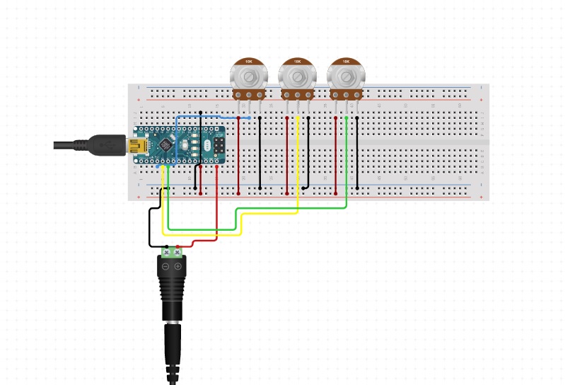
Currently, I just connect the ADC input with a variable resistor to simulate the voltage input to the ADC. but the ADC value doesn't change when I turn the variable resistor.
And the voltage range you saw on the meter is WHAT?
You muse see zero at one end of travel and the power supply voltage connected to the opposite end. DO you have the power ground connected to one end of the pot?
/*
  This experimental code shows how to control the nRF52840 SAADC using a Timer and PPI.
  The SAADC uses EasyDMA to copy each sample into a variable in memory.
  The ADC samples pin A0.
  Note:
  - the maximum sampling rate is 200kSamples/s
  - only one sample per second it printed
  - this code has not been tested with a debugger, some samples might be lost due to mbedOS (needs further testing)
  - this code will likely not work when using analogRead() on other pins

  The circuit:
  - Arduino Nano 33 BLE/ BLE Sense board.

  This example code is in the public domain.
*/

#include "mbed.h"

#define SAMPLES_PER_SECOND  180000
#define PPI_CHANNEL         (7)

#define ADC_BUFFER_SIZE     3
volatile nrf_saadc_value_t adcBuffer[ADC_BUFFER_SIZE];
volatile bool adcFlag = false;

volatile uint32_t sampleCounter = 0;


void setup()
{
  Serial.begin( 9600 );
  while ( !Serial );
  //Serial.println( "Arduino Nano 33 BLE (mbedOS) example: Timer -> PPI -> SAADC" );
  Serial.println( "A0\tA1\tA2" );
  initADC();
  initTimer4();
  initPPI();
}

void loop()
{
    Serial.print( adcBuffer[0] );
    Serial.print( '\t' );
    Serial.print( adcBuffer[1] );
    Serial.print( '\t' );
    Serial.println( adcBuffer[2] );
}


extern "C" void SAADC_IRQHandler_v( void )
{
  if ( NRF_SAADC->EVENTS_END != 0 )
  {
    NRF_SAADC->EVENTS_END = 0;
    adcFlag = true;
    sampleCounter++;
  }
}


void initADC()
{
  nrf_saadc_disable();

  NRF_SAADC->RESOLUTION = NRF_SAADC_RESOLUTION_12BIT;
  // P0.04 - AIN2 -> Pin A0
  NRF_SAADC->CH[2].CONFIG = ( SAADC_CH_CONFIG_GAIN_Gain1_4    << SAADC_CH_CONFIG_GAIN_Pos ) |
                            ( SAADC_CH_CONFIG_MODE_SE         << SAADC_CH_CONFIG_MODE_Pos ) |
                            ( SAADC_CH_CONFIG_REFSEL_VDD1_4   << SAADC_CH_CONFIG_REFSEL_Pos ) |
                            ( SAADC_CH_CONFIG_RESN_Bypass     << SAADC_CH_CONFIG_RESN_Pos ) |
                            ( SAADC_CH_CONFIG_RESP_Bypass     << SAADC_CH_CONFIG_RESP_Pos ) |
                            ( SAADC_CH_CONFIG_TACQ_3us        << SAADC_CH_CONFIG_TACQ_Pos );

  NRF_SAADC->CH[2].PSELP = SAADC_CH_PSELP_PSELP_AnalogInput2 << SAADC_CH_PSELP_PSELP_Pos;
  NRF_SAADC->CH[2].PSELN = SAADC_CH_PSELN_PSELN_NC << SAADC_CH_PSELN_PSELN_Pos;

  // P0.05 - AIN3 -> Pin A1
  NRF_SAADC->CH[3].CONFIG = ( SAADC_CH_CONFIG_GAIN_Gain1_4    << SAADC_CH_CONFIG_GAIN_Pos ) |
                            ( SAADC_CH_CONFIG_MODE_SE         << SAADC_CH_CONFIG_MODE_Pos ) |
                            ( SAADC_CH_CONFIG_REFSEL_VDD1_4   << SAADC_CH_CONFIG_REFSEL_Pos ) |
                            ( SAADC_CH_CONFIG_RESN_Bypass     << SAADC_CH_CONFIG_RESN_Pos ) |
                            ( SAADC_CH_CONFIG_RESP_Bypass     << SAADC_CH_CONFIG_RESP_Pos ) |
                            ( SAADC_CH_CONFIG_TACQ_3us        << SAADC_CH_CONFIG_TACQ_Pos );

  NRF_SAADC->CH[3].PSELP = SAADC_CH_PSELP_PSELP_AnalogInput3 << SAADC_CH_PSELP_PSELP_Pos;
  NRF_SAADC->CH[3].PSELN = SAADC_CH_PSELN_PSELN_NC << SAADC_CH_PSELN_PSELN_Pos;

  // P0.30 - AIN6 -> Pin A2
  NRF_SAADC->CH[6].CONFIG = ( SAADC_CH_CONFIG_GAIN_Gain1_4    << SAADC_CH_CONFIG_GAIN_Pos ) |
                            ( SAADC_CH_CONFIG_MODE_SE         << SAADC_CH_CONFIG_MODE_Pos ) |
                            ( SAADC_CH_CONFIG_REFSEL_VDD1_4   << SAADC_CH_CONFIG_REFSEL_Pos ) |
                            ( SAADC_CH_CONFIG_RESN_Bypass     << SAADC_CH_CONFIG_RESN_Pos ) |
                            ( SAADC_CH_CONFIG_RESP_Bypass     << SAADC_CH_CONFIG_RESP_Pos ) |
                            ( SAADC_CH_CONFIG_TACQ_3us        << SAADC_CH_CONFIG_TACQ_Pos );

  NRF_SAADC->CH[6].PSELP = SAADC_CH_PSELP_PSELP_AnalogInput6 << SAADC_CH_PSELP_PSELP_Pos;
  NRF_SAADC->CH[6].PSELN = SAADC_CH_PSELN_PSELN_NC << SAADC_CH_PSELN_PSELN_Pos;

  NRF_SAADC->RESULT.MAXCNT = ADC_BUFFER_SIZE;
  NRF_SAADC->RESULT.PTR = ( uint32_t )&adcBuffer;

  NRF_SAADC->EVENTS_END = 0;
  nrf_saadc_int_enable( NRF_SAADC_INT_END );
  NVIC_SetPriority( SAADC_IRQn, 1UL );
  NVIC_EnableIRQ( SAADC_IRQn );

  nrf_saadc_enable();

  NRF_SAADC->TASKS_CALIBRATEOFFSET = 1;
  while ( NRF_SAADC->EVENTS_CALIBRATEDONE == 0 );
  NRF_SAADC->EVENTS_CALIBRATEDONE = 0;
  while ( NRF_SAADC->STATUS == ( SAADC_STATUS_STATUS_Busy << SAADC_STATUS_STATUS_Pos ) );
}


void initTimer4()
{
  NRF_TIMER4->MODE = TIMER_MODE_MODE_Timer;
  NRF_TIMER4->BITMODE = TIMER_BITMODE_BITMODE_16Bit;
  NRF_TIMER4->SHORTS = TIMER_SHORTS_COMPARE0_CLEAR_Enabled << TIMER_SHORTS_COMPARE0_CLEAR_Pos;
  NRF_TIMER4->PRESCALER = 0;
  NRF_TIMER4->CC[0] = 16000000 / SAMPLES_PER_SECOND; // Needs prescaler set to 0 (1:1) 16MHz clock
  NRF_TIMER4->TASKS_START = 1;
}


void initPPI()
{
  NRF_PPI->CH[PPI_CHANNEL].EEP = ( uint32_t )&NRF_TIMER4->EVENTS_COMPARE[0];
  NRF_PPI->CH[PPI_CHANNEL].TEP = ( uint32_t )&NRF_SAADC->TASKS_START;
  NRF_PPI->FORK[PPI_CHANNEL].TEP = ( uint32_t )&NRF_SAADC->TASKS_SAMPLE;
  NRF_PPI->CHENSET = ( 1UL << PPI_CHANNEL );
}
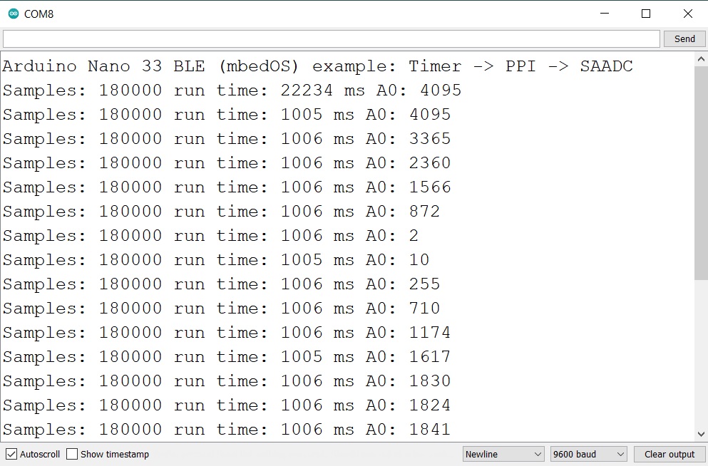
I set the first pot (A0) at the minimum voltage, the second pot (A1) at around the middle voltage, and the third pot (A2) at maximum voltage, the result is like the picture below: