pH and ISE electrodes have very high impedance and very low current. It's always a good idea to look for application notes for difficult sensor scenarios rather than just off the cuff "rail to rail" favorite op amp recommendations that still may not be suitable due to offset voltage, input bias, or common mode rejection limitations.
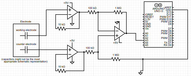
Thanks all. I went ahead and built an instrumentation amplifier and it is able to provide the expected gain when I supply the inputs with a simple voltage (sourced from voltage divider) but not when I supply the inputs with my electrode (that produces voltages of approximately same scale (10s of mV). Here's a picture of my circuit showing the important things -- note I'm not certain that a couple capacitors best represent the behaviour of the electrodes but it seems possible.
I also tried putting resistors between one and/or both inputs and ground to prevent charge accumulation from bias current, but that still didn't yield the wanted result. Using a voltmeter, I measure across the inputs and find that their difference is zero even when electrode is connected and expected to be producing the mV potential.
I can provide more info if requested ... I'm trying to explain the key things I've noticed.
When the electrode's potential difference is measured just by a voltmeter, it gets ~20mV. When connected to the circuit, there's no observed difference so it is as if the expected charge on electrodes is getting depleted into the instrumentation amplifier, but I thought the first two op amps are meant to buffer that (with ideal resistance being infinite) so I'm not sure what's happening... Any more insight is appreciated.
I assume when you measure with the meter you are actually grounding one of the electrodes.
also when you supply the inputs with a simple voltage (sourced from voltage divider) and get sensible results one of the electrodes is grounded?
When the electrode's potential difference is measured just by a voltmeter, it gets ~20mV.
thats with the op amps disconnected.
.. but with the circuit connected as shown AND the meter acreoss the electrodes you get zero.
Your diagram shows the cell is completely isolated - as if you had two elecrodes and nothing else in a glass beaker of liquid. I'm wondering if that is actually the case? Or is this part of a larger liquid circuit with other connections - maybe to ground, as if the beaker was metal and grounded?
I'd suggest you try biasing your "counter electrode" to Vcc/2 to ensure the op amps are working in their linear region.
When I measure with the meter, I do not ground either electrode.
When I supply a voltage divider's potential to test that amplification works in that case, I have the electrodes disconnected altogether.
That is correct: with the circuit connected as shown AND the meter across the electrodes it reads 0.
It is the case that the cell is completely isolated like you ask about.
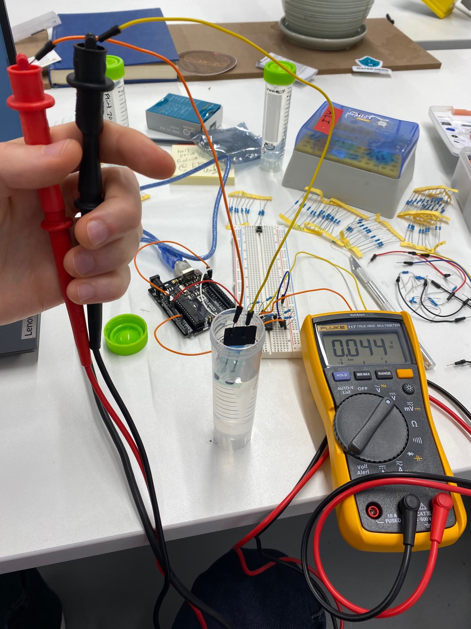
Here a have some photos that might help find the issue:
Fig 2. In same solution but connected to instrumentation amplifier circuit, the voltmeter reads 0.026V (this value isn't important nor expected to match the value in figure 1) but reading analog input A3 outputs to the arduino editor monitor a value of 0.05V.
Fig 3. Using a voltage divider that supplies 0.016V across the IA inputs results in the analog input A3 to output the expected value of 0.16V (10x gain in this case).
Any ideas?!
edit: sorry this contradicts in my last post when I said, "I measure across the inputs and find that their difference is zero even when electrode is connected and expected to be producing the mV potential." However, the problem persists that the output is unexpected as described.
You need to ensure the input potential to the IA lies between 0V and Vcc so I'd suggest you bias point B to +2.5V.
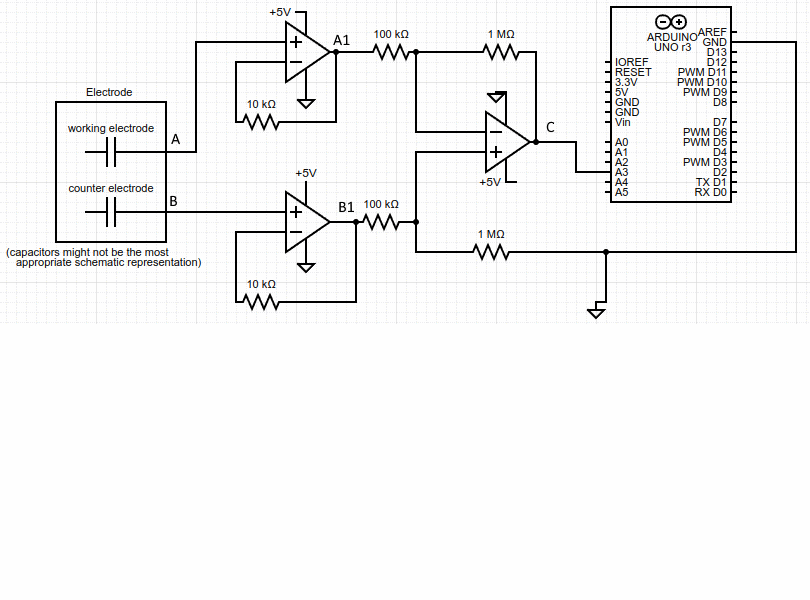
Then using your DVM if you can measure each voltage A, B , A1, B1, C with respect to 0V.
Your IA has a gain of 10 so if the electrode potential A-B = 20mV you should see
B = B1 = 2500 approx
A = A1 = 2520mV approx
C = 2500-200 = 2300mV
Your fig doesnt show the type of op amp - which ones are you using? I've just been testing one today (CA3130) that had me puzzled until I relaised it was not unity gain stable.
Thanks for this. I'm on vacation so I won't be able to attempt it until next week.
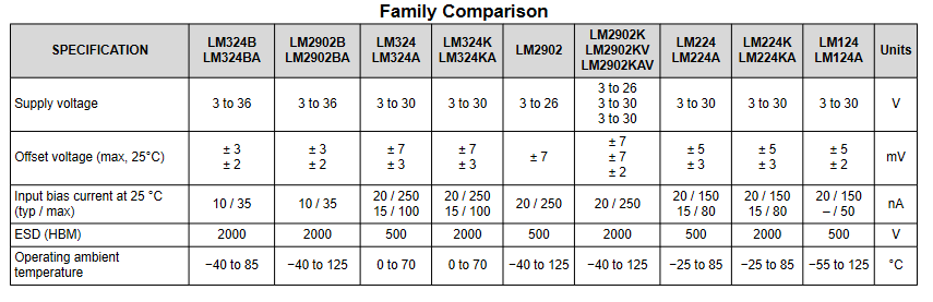
I've been using the LM224AN quad op amp.
Also, how are you getting that calculation for 'C'? Actually, I'm expecting B-A=20mV (as opposed to in your message 'A-B'), so then I would expect the output to be 10x the difference of the input, thus C=200mV.
If you are using Vcc/2 as your reference then the output voltage will also be with respect to that voltage. And of course the 1M from the op amp + input will also go there, not to ground as shown in your fig.
I'd not go with Leo's suggestion of using the 3V3 as a refernce because the ourput is NOT rail -rail to V+, I'd still choose to use a 1:1 divider on the rails to give Vcc/2.
The output voltage swing when run single supply 5V is also a concern.
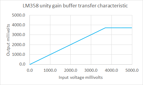
This is a transfer characteristic I measured on an LM358 wired as a unity gain buffer
you can see the output voltage can not exceed 3.7 volts (ie Vcc-1.3V)
I'd be happier if you used a suitable CMOS op amp such as the MCP6022 which is fully rail-rail, and has Ibias of <1pA and a low input offset voltage - about 1mV.