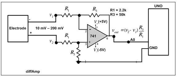
Hi all, I want to measure the potential difference that develops between electrodes (of an ion selective electrode so one of the two is exposed to a greater ion concentration that charges it on the order of tens of millivolts). I think that the electrodes could therefore be considered as a high impedence low voltage source so I seek to measure that voltage to a reasonable precision (accuracy would be good too but is less immediately important because I can simply implement an offset) and stability/noise that for starters could be the 3.3V arduino (nano ble) operating voltage divided by 10bit analog input --> ~3mV resolution. Here is an image depicting how I think the circuit might generally need to be:
The diode is meant to protect a reversed input that could damage the board. I'm not sure if I'm missing something(s) or how I should go about deciding the resistor, diode, and op (differential) amp's specifications... If someone could please with feedback and guidance toward the correct path forward, I would much appreciate that. Thanks,
edit: The voltage source and resistor in image are meant to represent how I think the electrodes behave... I don't know approximately the resistance value but think it could be high or low depending on the salinity of the aqueous solution being measured... should I perhaps be attempting to measure this value to get greatest performance? Right now I'm more focused on basically functioning than being able to function in all use-cases.
I recommend to use differential amplifier similar to Fig-1. If using 3.3V Arduino, then use +3.3V and -3.3V supplies for the op amp. You need to calibrate your electrodes against known 2-point which are concenration-1 and concentration-2.
This is great if it is really so simple - thank you. If you don't mind, how might be a reasonable way to supply pin 4 with the -3.3V? A quick search is guiding me toward possibly using PWM or an external voltage source. And yes I understand and intend to do that 2-point calibration!
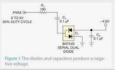
It is better that you use -3.3V from an external adjustable supply with GND-pin connected with Arduino. Alternatively, you can use a charge pump using PWM signal of Arduino which is complicated as you have to build the charge pump (Fig-1). Chang the duty cycle to reduce the output voltage.
Figure-1:
You probably want to use something newer than a 741 op amp. Does it even work well with +5 and - 5V? I think the lowest I ever went was +12,-12 - that was 50 years ago, so memory is a bit hazy.
It isn't. The truly ancient 741 op amp identified in that schematic won't work well, and the amplifier input impedance of that circuit is probably far too low for your probe.
Please post a link to the product page or data sheet for the probe.
For this application you need a FET rail-to-rail op amp. Do you want to measure both positive and negative voltage? Or it is known one voltage is always higher than the other? What bandwidth do you need?
@graemedrinkable
Try with something simple as per doctrine of AE and then gradually moves to the complex one. When this SSS Strategy is followed, it is certain that the project will end up with success.
generally +-12V supplies are inconvenient.
You need to condition the signal from your sensor to a voltage that lies within the range of the ADC.
The sensor can produce a voltage in either direction.
The easy way to do this is to use a circuit like this:
that will give a value of 3.3V /2 for 0V input.
You can choose R2/R1 to give the gain you need, that will keep the voltage within the ADC range.
To get a higher input resistance you could go to R2=100M.
I'd suggest you choose an op amp from the table in that tutorial - say an MCP6002
A 741 will not give a suitable output with single ended or even +-3.3V supplies. Dont bother generating a negative supply, there is no need with modern rail-rail op amps.
These are excellent op amps and currently my favorite. They are slow, but very low power and perfect for many Arduino applications, especially battery powered. Still available in PDIP packages for breadboards! $0.43 at Digikey
no. its pin-out is the same (pretty standard for dual op amps in a DIL8 package) but the characteristics are very different.
My car has 4 wheels but a ferrari it isnt.
Thanks everyone for the replies, I am looking into all the suggestions in effort to proceed appropriately. I didn't share the electrode's datasheet as it is a custom built part so only I can gather properties about it. I checked the resistance across the electrodes when in solution (as they'll be used) and found it to be in excess of 10Mohms. Further research leads me now to believe that the electrodes act like a capacitor (polarizable electrode) and that they'd easily discharge. Therefore, I'm in progress of learning how to build out the measuring circuit which I think must include buffers, an instrumentation amplifier, and probably also a reference voltage component... There is much I must learn still so I appreciate the resources you've all shared.
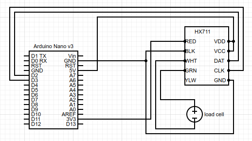
Start with something and then keep adjusting the setup for improved performance. The HX711 Module could be a good choice as it accepts very low (mV range) differential signal and then amplifies it. The interfacing with UNO is also simpler.
HX711 might be good as I recall our ex-electrical eng. describing how the load might resemble a Wheatstone bridge... In that case, could a simple starting point look like this?:
(the HX711 breakout board taken from SparkFun Load Cell Amplifier - HX711 - SEN-13879 - SparkFun Electronics)
And is CLK even necessary?