Hello,
Recently I made a device which was a 1535 seven segment who could show the temperature of an industrial oven using a PT100 sensor. It worked fine with a reasonable error about 3 degrees and client told me that its OK, but after few weeks he told me he the device showing different temperature from a commercial industrial temperature controller.
So I went to see the device, the calibration multi-turn potentiometer was turned a bit and I fixed it, and it was good to go with the 3 degree error, I also measured the sensor resistance and everything was correct,
In this time, my Arduino was showing 97C, but the commercial controller was showing about 130C.
I also measured the another PT100 connected to commercial controller and it had the same resistance as the one connected to my device.
Then I measured the oven temperature with two different sensors and it was 130C, so there is something wrong with my calculations?
I based my calculations on this table:
And with this table, my output temperature is acceptable, then why this problem happened!?
you can search for PT100 resistance table and see lots of tables like this, the values are all the same
The wiring and voltage measurement with these sensors is important for accuracy .
Normally sensors are 4 wire , a small current passes through two of them and the voltage measured across the other two - this stops lead resistance and contact resistance affecting the reading.
Usually an amplifier is used to increase the measured voltage .
By putting values from resistance table in Excel and getting the formula.
jremington:
And why would you round off the average?
I dont actually remember but I think it was because because my seven segment would just pop through very not accurate value or something like that and it got fixed by rounding that value.
jremington:
   float PTress= (PTres1+PTres2+PTres3)/3;  //calculating the average
    PTres = round(PTress);
    Temp= ( PTres * 2.6 ) - 260; //calculating the temperature
Fitting a few values around 100 C to the table, I get
Temp = PTres*2.632 - 264.5;
I did exactly what you have done, and got the same formula, but try and put some numbers in it and check it with the resistance table, the R×2.6-260 is more accurate I dont know why, I just found it out randomly while messing with the code.
hammy:
The wiring and voltage measurement with these sensors is important for accuracy .
Normally sensors are 4 wire , a small current passes through two of them and the voltage measured across the other two - this stops lead resistance and contact resistance affecting the reading.
Usually an amplifier is used to increase the measured voltage .
I dont know about 4 wire sensors but mine is a 3 wire one, which as you know two of the wires are just connected to one head of the PT100 resistor, I just shorted them together.
but running current through the resistor is also a great way to measure the resistance I never thought about it thanks...
aarg:
How about saving us a lot of work and explaining how you translated the table to code? In words and math, not code.
Yes sorry my bad, I explained in comment 6#
As I said my output value is acceptable but anyway I will add a 16bit ADC and a Wheatsone bridge to it for more accuracy later, Ill post another topic for that for sure soon cuz I need help with that too,
but right now I just want to know whats the reason of the difference between the commercial temperature controller and my circuit.
Certainly not for the limited data set I fitted and plotted, by definition. The plot shows how accurate the fit is (the rms error is about 0.03 percent).
But the result of using either equation will be about a factor of 100 more accurate than this result:
my Arduino was showing 97C, but the commercial controller was showing about 130C
I was thinking to use a Wheatstone bridge, does it worth trying with a UNO or should I buy a 16bit ADC first?
will the difference be even noticed by the UNO ADC? I need at least 0.1 Ohm resolution
Using the sensor as you do , with the connection at one end wired together means the resistance of the wiring to the sensor adds to that if the sensor creating an additional error in reading
Setrik_aZ:
I dont know about 4 wire sensors but mine is a 3 wire one, which as you know two of the wires are just connected to one head of the PT100 resistor, I just shorted them together.
but running current through the resistor is also a great way to measure the resistance I never thought about it thanks...
Hi,
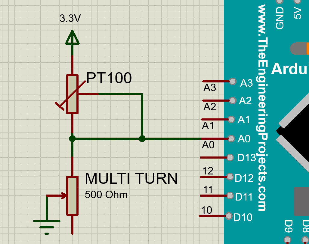
Can you please post a copy of your Arduino circuit, in CAD or a picture of a hand drawn circuit in jpg, png?
How did you measure the resistance with your Arduino?
(I know that's not the correct way to connect a resistor I considered that potentiometer as a 3 wire PT100 and shorted the 2 already shorted wires, also the 500 Ohm potentiometer is a multi turn to reach the exact 500 Ohm value)
then I read the voltage and calculate the resistance with this formula
Rx=(R1.Vin/Vout)-500
What is the temp range you want to measure.
The fixed resistor is normally the same value as the thermistor is in the middle of the temp of interest.
So if the oven is set between 100C and 160C, you would use a 150ohm fixed metal film resistor (not a trimpot).
You get the most A/D values per degree C that way, but did you actually calculate that...
I only get 18 A/D values from the 10-bit A/D between 130C and 160C.
That's only one A/D value per 1.6C, which gets worse the more you deviate from that centre temp.
You should connect the PT100 between pin and ground, and the fixed resistor between pin and 3.3volt,
So you don't run the risk of shorting VCC to ground.
Code must be changed for that.
You should use a Steinhart-Hart formula to convert PT100 resistor value to temp.
Leo..
Wawa:
You get the most A/D values per degree C that way, but did you actually calculate that...
I only get 18 A/D values from the 10-bit A/D between 130C and 160C.
That's only one A/D value per 1.6C, which gets worse the more you deviate from that centre temp.
Sorry what do you mean by 18 A/D values?
Wawa:
You should use a Steinhart-Hart formula to convert PT100 resistor value to temp.
Whats that? you mean using the equation i'm using now (R*2.6351-264.49) is wrong?