My project would be to control two DC motors with 2 rotary encoder modul following the speeds on the display, also option to choose preset engine speeds from SD card (which can be put behind the LCD).
I could program and use the shields individually, though this is new for me, so I accept any advises.
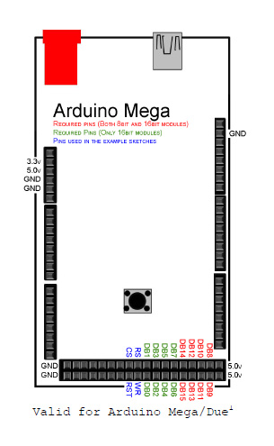
The PINs left are:
Analog In: A0-A5 , A8-A15
Communication: 14-21
Digital : 8-13 , GND, AREF, SDA, SCL
Nice pictures but they are meaningless to me. Post an annotated schematic showing how you have connected these parts together and post links to there technical information. On the schematic be sure to show all connections, power, ground, power sources and any other hardware connected.
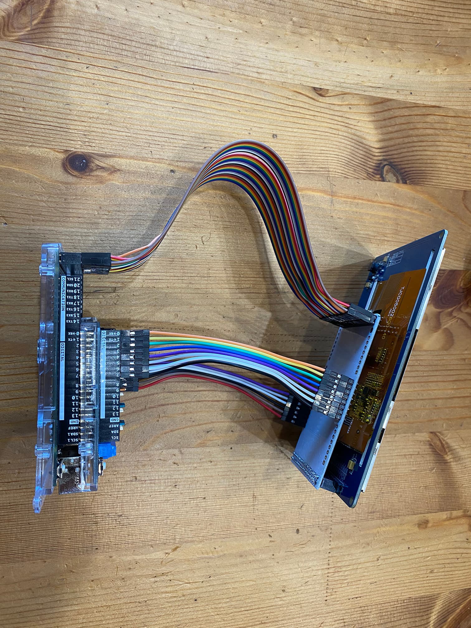
Your wiring looks very neat and that you took time to do it correctly, good job assembling it.
According to the online documentation for the motor shield, it uses D3 as a PWM signal for channel A.
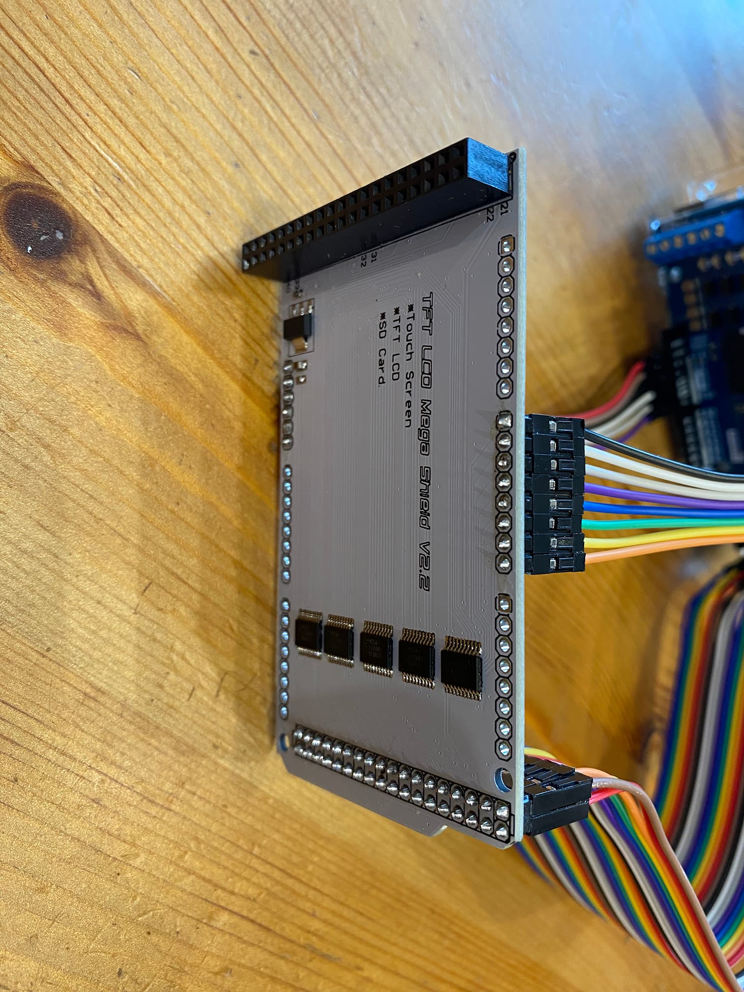
Your photos appear to show D3 also going to the board that the LCD plugs in to.
If your LCD really needs D3, then that would be a problem. You should look at the LCD documentation to see if it's really used. Also check out the library for the LCD to see if it's possible to use another pin that the motor shield doesn't use. Potentially that could mean modifying the library code.
gilshultz I dont have any schematic yet for the whole project, I just tested the LCD "hello world" style when I connected the display shield sets together, and also separatly tested the motor shield to see if the motor starts to spin. I tested the rotary encoder with Uno and 3 LEDS changing each LED I twisting the encoder. All simple test run correctly.
This would be the first try as stacked up I would like to test display again, but I'm worried that I don't know about something that's missing and one of the parts will break down. After I would test the motor again, then I may test them together.
What software would you recommend where I can build and test arduino circuits with shields?
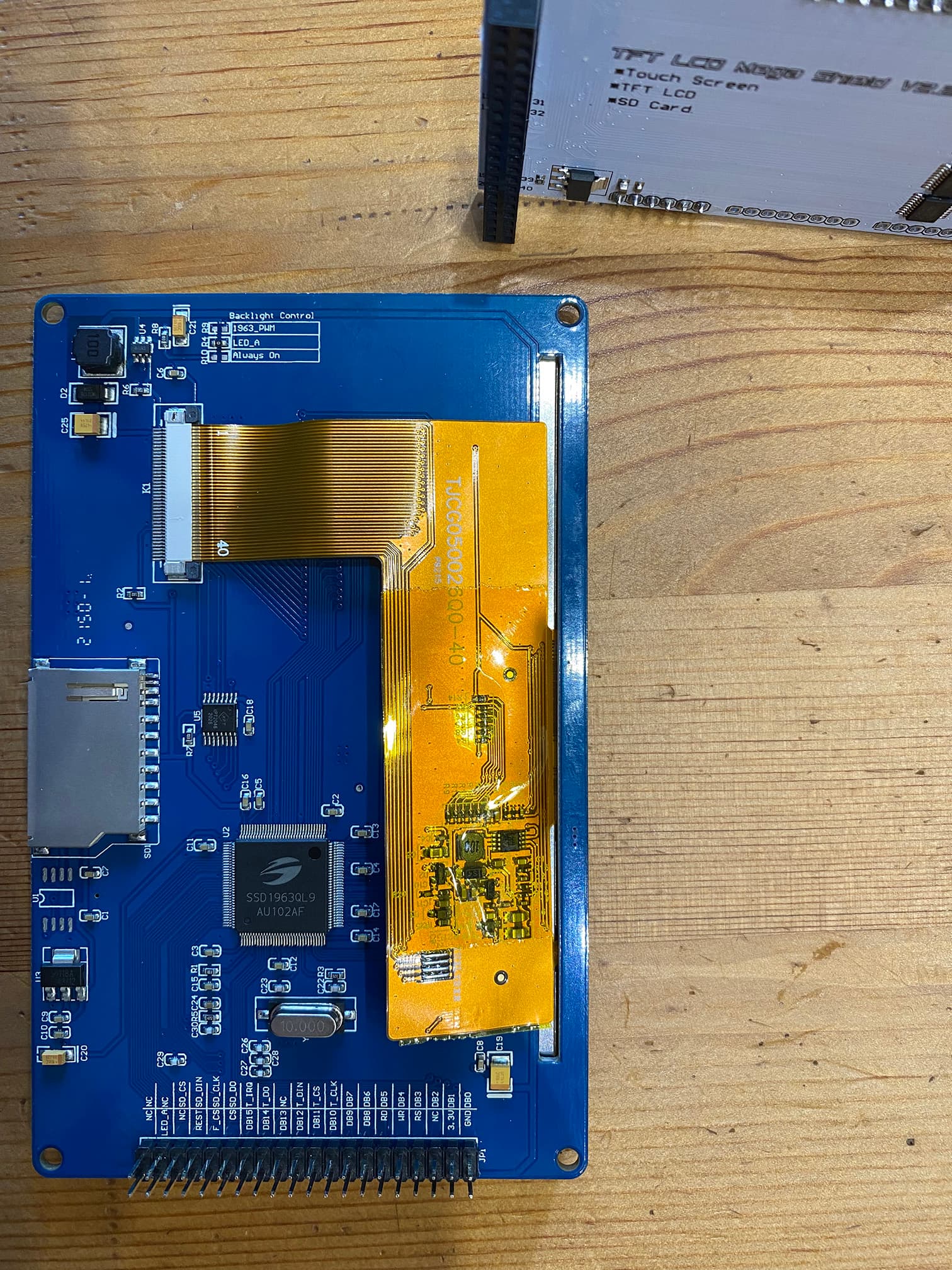
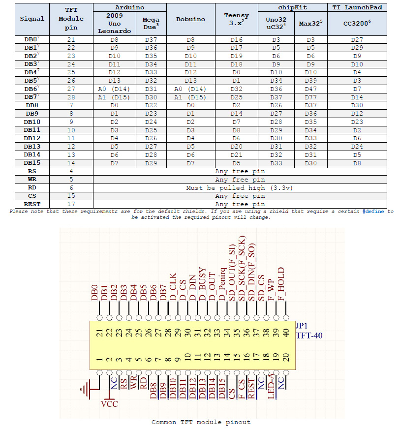
markd833 I wired the TFT shield as it was connected to Mega by itself, I didn't check yet which connections I would really need. In UTFT.h's documentations I found that the program uses these pins for 8bit LCD on Mega:
Pins: D22-D37
Any pin : RS, WR, RD (3.3V), CS, REST
That is OK just do a partial schematic. As for software most libraries have example programs with them. There are many examples included with your IDE, mouse to file>examples.
If you are serious about electronics down load a copy of KiCad, it is a complete schematic capture program, it will take you all the way through including the Gerber files needed to make a PCB. It is not a one night learn type of program. The price is very affordable, a complete non limited version is free. They will ask for a non mandatory donation.
A great investment for you is the Arduino Cookbook it is what I used when I learned Arduino. The worst thing you can do is connect the motor to the Arduino, it tends to fry them. You are doing it correctly with the motor shield and getting parts to work as you connect them.
I downloaded the KiCad 9.0, but it seems to raw for me yet. Also it doesn't have the Mega and any shield schematic, and I'm so rookie that I can't make work the uploaded Professor-Mayhem's made schematic:
Also downloaded the Arduino Cookbook, it will take a couple of days to learn something that I would use now. So I'll get back.
Take your time and enjoy the read. It might get costly if you find a bunch of projects you want to build. Spend maybe 15 minutes with KiCad each day, doing in it slowly it will stick and become second nature.