I'm building a MIDI controller using a Leonardo to start, but eventually a Pro Micro, to work as an accessibility device for a synth. It will need to have a lot of components on it.
I'm curious about the best way to wire up all these seven segment displays. I'm looking at using either
MCP23017 on the I2C protocol
MAX7219 on the SPI protocol
I'm worried about overloading I2C with too much work and then everything being a little slow, but I don't really have a concept about how fast the protocol is.
With the MAX7219's I would need two of them and I can't find a diagram on how to wire multiple of those up. Where as the MCP23017 I would also need two but the wiring is more straight forward.
I'm very new at this side of engineering so forgive me if I'm missing something major here. Can someone point me in a direction on how to handle this many seven segments?
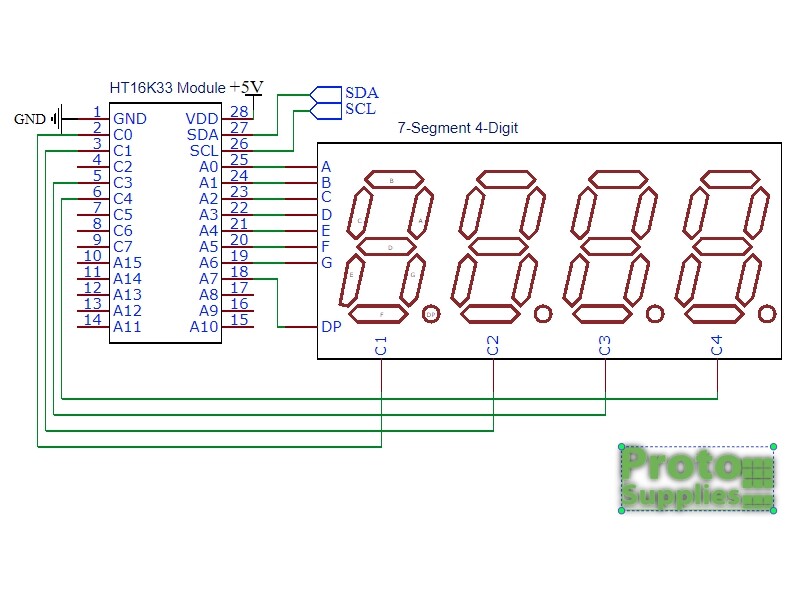
Have you looked at the HT16K33 for driving the seven-segment displays?
Note that the same chip can be used at the same time to scan a 39 key keypad (wired as a 3 x 13 matrix).
I hadn't seen this chip! thank you. wondering if you are aware of some examples of it getting wired up with a handful of seven seg displays? not finding anything on first pass. I also see that it has some issues after you put 8 displays on it, something about needing to write a little custom code to access additional displays. I'm comfortable with that, just not so much the wiring.
I'll have to search a bit to see if I can find any examples with large numbers of seven-segment displays. Probably more common to treat it as a 16x8 LED matrix and handle the seven-segment patterns yourself.
I would probably avoid the MAX7219 with SPI, that would need separate chip select lines for each chip, and by the looks of it you are using almost every pin.
Where do you see "issues" with the HT16K33 ? Just use two HT16K33 for your 12 digits and the program will be straight forward.
By the way,just in case the MAX7219 were still on your short list: the MAX7219 can be daisy chained and so two MAX7219 still only need one CS line. The Datasheet page 13 shows a diagram.
No, you can daisy-chain many max7219 chips, only one chip select line needed for many chips.
If course, if you daisy-chain maybe 15+ of the chips, you will run into fan-out problems and need to use buffer chips on the CLK and CS lines, but still only one CS pin needed.
EDIT: sorry, @noiasca , you covered this in your post.
Well, both ways a legit.
Imho adding the second IC is done in minutes.
On the other hand, one must be very confident and fast in C++ programming to make the additional pins working in "minutes" while keeping a nice useable interface.
By the way, I would use my HT16K33 library which can handle several HT16K33 as "one" display if necessary
display.print(F("even a long text expanding over up to 8 modules"));