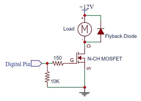
ok hope I am doing this correctly. wiring diagram. plus 2 codes. one for each board.`
type or paste code here

FIRST CODE UNO
// this code with a UNOR3 board with MIDI shield on top (linksprite brand).
// MIDI OUT keyboard to MIDI IN shield.
// to receive incoming MIDI on channel 10 (from drum machine on keyboard).
// receiving OK and flashing LED13 to tempo of music beat. ALL GOOD.
// QUESTION: HOW DO I CONVERT THIS FLASHING LED TO CONTROL THE SPEED OF A SMALL DC MOTOR?
// assume I need to somehow map the flashing signal? to produce and output voltage (0-255)?
// Note also .. the motor is driven by a second Arduino MEGA board with Arduino REV3 motor controller sitting atop.
#include <MIDI.h>
MIDI_CREATE_DEFAULT_INSTANCE();
#define LED_PIN 13;
void setup() {
pinMode(13, OUTPUT);
Serial.begin(31250);
MIDI.begin(); // Launch MIDI and listen to channels
}
void loop() {
if (MIDI.read(10))
; // If we have received a message
{
switch (MIDI.getType()) {
case midi::NoteOn:
digitalWrite(13, HIGH);
delay(10);
  case midi::NoteOff:
    digitalWrite(13, LOW);
    delay(10);
SECOND CODE MEGA
// MEGA board. Arduino REV3 motor shield on top. One DC motor (5 volts) with external power supply via shield.
#include <AFMotor.h>
int speedPotPin3 = A3; // speed of DC motor via potentiometer on A3
int speed3;
void setup() {
//Setup Channel A.
pinMode(12, OUTPUT); //Initiates Motor Channel A pin
pinMode(9, OUTPUT); //Initiates Brake Channel A pin
Serial.begin(9600); // Initialize serial communication
}
void loop() {
speed3 = map(analogRead(speedPotPin3), 0, 1023, 0, 255);
digitalWrite(12, HIGH); // motor A : DIRECTION clockwise
digitalWrite(9, LOW); //Disengage the Brake for Channel A
analogWrite(3, speed3); //Spins the motor on Channel A at stated speed via INPUT A3 (potentiometer)
delay(200);
Serial.println(speed3);
delay(50);
}
[TEST_ArduinoShieldREV3_1DCmotor.ino|attachment](upload://anEMw6JkBbMunsumvo2Y2Vt2KZf.ino) (786 Bytes)
Not sure my diagram uploaded I will try again.