jamesklyne:
Here is a link to the library I modified to work so far:
https://drive.google.com/file/d/0B--LGPrqJ1QzVmo3MFpUc2FQNW8/view?usp=sharing
What exactly did you modify to get it to work?
The older library wasn't working for me: Primarily I was getting tons of 0s, some random numbers and occasionally something that looked like the correct number.
In the Digimatic library I was able to fix my problem by holding the request pin low until the message was finished sending. This was on a Digimatic Absolute Indicator, though I'm not sure exactly if/how that matters. This is what I did to the digimatic.cpp:
double Digimatic::fetch()
{
        long looptime_l = micros();
        int timeout = 300; // should take <35ms total to fetch data
        // trigger request
        digitalWrite(req_pin,LOW);
        //delay(50); <=REMOVED THIS
        //digitalWrite(req_pin, HIGH); <=REMOVED THIS

        unsigned long lastrequest = millis();

        for(int i = 0; i < 13; i++ ) {
            int k = 0;
            for (int j = 0; j < 4; j++) {
              while( digitalRead(clk_pin) == LOW && lastrequest>(millis()-timeout) ) {
              } // hold until clock is high or timeout
              while( digitalRead(clk_pin) == HIGH && lastrequest>(millis()-timeout)) {
              } // hold until clock is low
              bitWrite(k, j, (digitalRead(data_pin) & 0x1)); // read data bits, and reverse order )
            }

            // store data
            rawdata[i] = k;
            digitalWrite(req_pin, HIGH); //<=ADDED THIS
        }
I have a new issue. I've tried to transfer the code from an Arduino Uno to a NodeMCU.
Everything works fine on my UNO, just not the MCU
Now all i get is zeros. My suspicion is that I've just got it wired wrong
One thing I don't think I've seen noted on this thread is that at least for me, it won't work at all without the ground to the sensor wired to the board.
If you do try this remember that the pins are essentially labeled wrong from the arduino IDE perspective. The GPIO pins are explained here: Arduino Project Hub
Is there something about the NodeMCU that's just different?
I saw at least one forum where they said you had to ditch the
#include <arduino.h>
to use nodemcu but that seems odd.
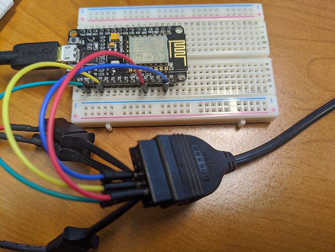
Connector:
Pin 1 GND => GRN
Pin 2 DATA => RED
PIN3 CLK => YLW
PIN5 REQ => BLU
NodeMCU:
D1=>BLU
D4=>RED
RX=>YLW
GND => GRN
Ive attached some photos
My previous reply somehow was deleted?
I've managed to fix it. As I suspected it was a wiring issue but I don't totally understand the result.
This is what didn't work:
Connector:
Pin 1 GND => GRN
Pin 2 DATA => RED
PIN3 CLK => YLW
PIN5 REQ => BLU
NodeMCU:
D1=>BLU
D4=>RED
RX=>YLW
GND => GRN
Pretty sure you can't use the Rx pin while you're trying to use serial monitor. Also the pin D4 corresponds to GPIO #2 which has the LED. I've read that the pullup doesn't work right when you're using that pin but haven't confirmed.
I have the modified code working in this configuration:
NodeMCU:
D2=>BLU
D3=>RED
D1=>YLW
GND => GRN
I also slowed it down considerably though I'm not sure if that is necessary.
Updated version of the changes I made:
/****************************************************************
 * Arduino Digimatic library - Version 1.0
 *
 * Copyright (c) 2014 Trevor Bruns.  All rights reserved.
 *
 * This library communicates with Mititoyo brand calipers via the Digimatic protol
 * Modified code from:  http://www.instructables.com/id/Interfacing-a-Digital-Micrometer-to-a-Microcontrol/?ALLSTEPS
 *
 * Changelog 1.0:
 * 9/25/14
 *	initial version
 * 6/26/20
 *  timeouts didn't seem to work using other tools so I adjusted some things, see comments below -d6
 *
 * This code is licensed under a GPLv3 License.
 *
 *******************************************************************************
 /
#include <Arduino.h>
#include <Digimatic.h>
#include <stdint.h>

 Digimatic::Digimatic(uint8_t clk, uint8_t data, uint8_t req)
 {
	clk_pin = clk;
	data_pin = data;
	req_pin = req;
	pinMode(clk_pin, INPUT_PULLUP); //simplified -d6
	pinMode(data_pin, INPUT_PULLUP); //simplified -d6
	pinMode(req_pin, OUTPUT);

	//digitalWrite(clk_pin, HIGH);     // enable internal pull ups
	//digitalWrite(data_pin, HIGH);  // enable internal pull ups
	digitalWrite(req_pin,LOW);     // set request at LOW
 }

double Digimatic::fetch()
{
        long looptime_l = micros();
        int timeout = 300; // should take <35ms total to fetch data //changed to 300, haven't found how fast I can make it -d6
        // trigger request
        digitalWrite(req_pin,LOW);
        //delay(5); //<=REMOVED THIS -d6
        //digitalWrite(req_pin, HIGH); //<=REMOVED THIS -d6

        unsigned long lastrequest = millis();

        for(int i = 0; i < 13; i++ ) {
            int k = 0;
            for (int j = 0; j < 4; j++) {
              while( digitalRead(clk_pin) == LOW && lastrequest>(millis()-timeout) ) {

              } // hold until clock is high or timeout
              while( digitalRead(clk_pin) == HIGH && lastrequest>(millis()-timeout)) {
              } // hold until clock is low
              bitWrite(k, j, (digitalRead(data_pin) & 0x1)); // read data bits, and reverse order )
            }

            // store data
            rawdata[i] = k;
            digitalWrite(req_pin, HIGH); //<=Added THIS and it worked on the UNO -d6
        }

        // convert from raw byte to double
        //  sign = rawdata[4];
        //  decimal = rawdata[11];
        //  units = rawdata[12];

        char buf[7];
        for(int lp=0;lp<6;lp++){
            buf[lp]=rawdata[lp+5]+'0';
        }

        long cur_value_int =atol(buf); //assembled measurement, sans decimal point and sign

        // convert to double w/decimal point
        char buf_dec[2];
        buf_dec[0] = rawdata[11]+'0';
        decimal = atol(buf_dec);
        double cur_value = (double)cur_value_int*(double)pow(10,-decimal);

        // check sign
        char buf_sign[2];
        buf_sign[0] = rawdata[4]+'0';
        int temp = atol(buf_sign);
        if(temp==8)
            cur_value = -cur_value;

        // units
        char buf_unit[2];
        buf_unit[0] = rawdata[12]+'0';
        temp = atol(buf_unit);
        units = (bool)temp;

        looptime_l = micros() - looptime_l;
        looptime_ms = (double)looptime_l/1000.0;

        return cur_value;
}

bool Digimatic::units_mm()
{
	return !units;
}

bool Digimatic::units_in()
{
	return units;
}

byte Digimatic::decimal_places()
{
	return decimal;
}

double Digimatic::looptime()
{
	return looptime_ms;
}
