Hi,
I have been doing some intense programming on MKR ZERO and MKR WIFI 1010 boards and have come across a potential issue, or potential feature of pins 11 and 12 (SDA and SCL) on those boards.
These pins seem to be pulled up to 3.3v all the time, even if I configure them as
pinMode(11,INPUT);
With NO OTHER CODE, no libraries, nothing, especially not Wire!
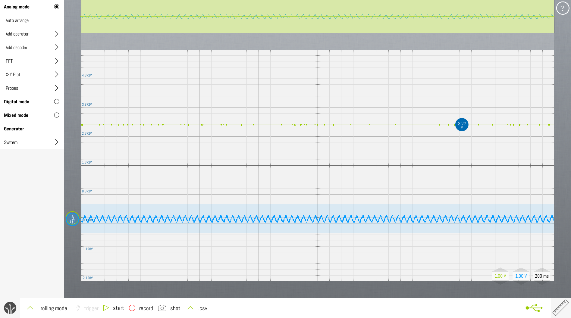
The attached oscilloscope image shows pin 3 in blue and pin 11 in green, both configured as simple INPUT. As one can see, pin 11 is pulled up to 3.3v and pin 3 is floating around 0v.
My questions are:
Is this normal behavior ? I have not seen the equivalent on the ATMEL based boards, but maybe I just failed to observe properly?
Is there any way to disable the pull up, or at least get the value of the resistance used?
Should I inform arduino.cc or do they already know about this and/or did they do this intentionally?
On the MKR WiFi 1010 they are not marked "DNP". The reason is that they are needed for the onboard ATECC508 crypto chip.
The MKR Zero actually has a footprint for the ATECC508, but it is "DNP" due to not being essential for a board without built-in networking connectivity. I think that's the reason why the pull-up resistors were marked DNP on the MKR Zero. It shouldn't be too difficult to remove those resistors on the MKR Zero. It's surface mount, but there isn't anything crowded too closely to the resistors.