Hi
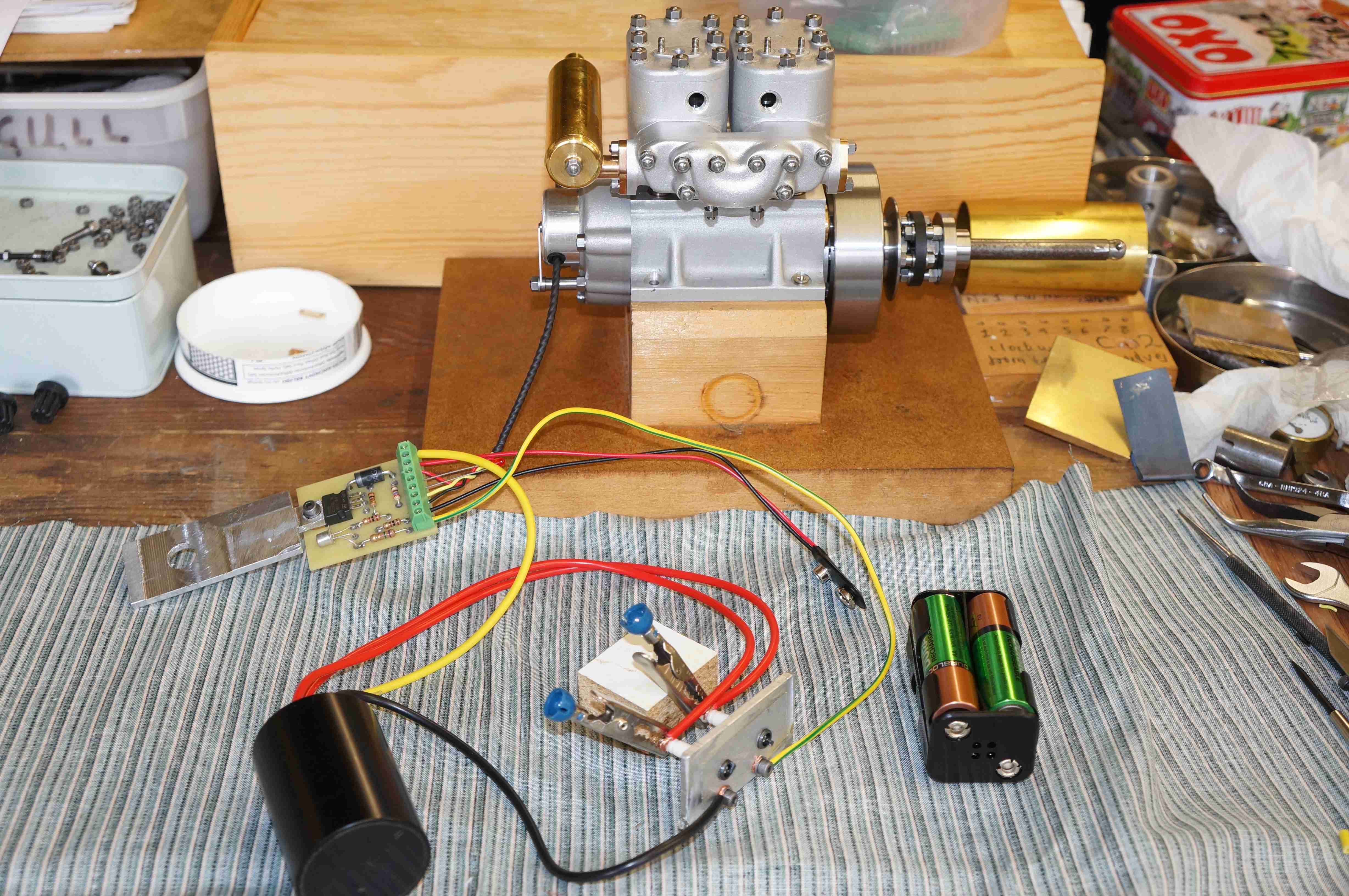
I would like some guidance with a simple engine management project. Just for context the photo shows the engine, with the ignition system being checked out. (Its a 10cc twin 4-stroke, water cooled.) I have also attached a block diagram of the intended electrical system.
I am proposing to use an UNO R3 for contol, as I think I should be able to cram all the functions in to one.
My current area of confusion is in trying to allocate pins (Arduino numbers). With my hazy grasp I think I need 11 & 12 for MISO & MOSI to drive the LCD display (as well as at least four more), but I am worried that might interfere with the timers.
I want to read two external interrupts which are hall sensor tacho pulses, one from the engine ignition circuit, and the other from the 4-pin pwm radiator fan, both running in the 10 to 100 Hz range. I also need a 25kHz PWM output for controlling the fan speed, based on an analog engine temperature input.
I am currently trying to get my head round the the register settings to do this, preferably using timer 2, but that seems to tie up pins 3 and 11, and the latter is I think needed, as I say, for the LCD.
Do I have a conflict?