Model railroad CTC panel, long distance com's to field nano's

My layout is in my basement. The CTC panel will reside upstairs in my office. I am using Nano's for automatic signal control already.

My plan is to use a Mega at the CTC panel for all the inputs (30 rotary switches, code button, etc), a Mega for all the LED's on the panel.
One of them will communicate out to the Nano's on the layout.

My question is which communication protocol would be best? Ethernet, or RS485?
Ethernet shields for both the Nano and Mega make the form-factor much better. An Enet switch downstairs for all the blocks to connect to seems like an easier idea than a ~600ft RS485 bus running around my layout.

Either way I need to learn how to implement either communication, but I want to make sure I'm going down the right path first.

either would work - you can get a ENC28J60 Ethernet Shield for the nano - saves having interconnecting wires giving poor connections and intermittent problems

also consider WiFi

Wifi didn't even cross my mind, but now it has. I'm already using a non-internet connected wifi router for my layout control so I could use that network.

I'll look into wifi shields. I started using Nano's as a "cheap" alternative to commercial signal products, and so I could write the logic. So if a wifi shield doesn't add too much cost I'll consider it.

Doesn't look like any direct wifi shields for a Nano exist.
Either way though I lose the SPI pins, that I was using for signal outputs on the Nano. Not a big deal, just changes the amount of Nanos I need in the field.

I think I'll be going down the Ethernet path for this.

look at using microcontrollers with WiFi builtin - saves all the messy wiring
e..g. ESP32 micros are powerful. plenty of flash and SRAM and have WiFi, Bluetooth Classic and BLE builti - cost about £7 in UK

I have a few ESP-WROOM-32's for my riding scale wifi controls. These where what the DCC-EX guys spec'd for me so I never looked into the GPIO capabilities.

But this got me thinking further into the future, and I don't think a Nano is what I really need in the field, at least for passing siding blocks. They work perfect for my signal drivers, but eventually I need to work switch controllers into the layout. A block with a siding right now uses up almost all the outputs just to drive the Green, Yellow, and Red LED's on 4 signal heads. There's no room to drive a couple servo motors, which means running multiple Nano's in those blocks.
It would be inefficient to write to one Nano for the signal to take siding, and another Nano to control the switch.

I'm beginning to think a Mega is what I need. A bit overkill, but there really isn't anything in between the Nano/Uno and Mega in regards to pin quantities right? This would allow me to have signal and switch drivers all in one Arduino.

At least I know now that Enet and/or Wifi will be a viable comm's so I don't have to run a billion wires off the CTC panel to the basement.
I have some re-thinking to do.

I use a Nano with up to 8 MCP23017 to get 128 I/O per node. I handle Tortoises, LEDs, block detection, and power relays that way. A bit of fiddling could allow more I/O, but at some point the Nano's memory becomes the limit. Although, you could use any number of shift register solutions as well to improve your signal count on the Nano.

I'm using JMRI with (presently) 6 RS485 Nano nodes with (typically) 4-6 MCP, a keypad, LCD, and a few discrete inputs. Final plans call for a total of 24-ish nodes, depending. If traffic gets burdensome, I'll just fork the RS485 network, creating two; JMRI can handle many. It's low tech, and decidedly antiquated, but the number of CMRI-style implementations running large layouts out there speaks to it's utility.
YMMV.

Are you soldering to the MCP23017 pins? I don't see any break out boards readily available for them... so that that means they are not an option for me. One of my requirements is I must be able to connect all wiring via screw terminals under the layout.

I'll keep that in mind though, maybe a solution will exist when I get around to finalizing hardware purchases.

And my requirement to have everything with screw terminals limits me in certain ways. I can't stack shields on the arduino and have a break out board. So, I have to hardwire the comms pins between the Mega and an Ethernet shield.

So with the Mega on a break out board, and the Ethernet shield on an Uno breakout board, there is not direct connection to the ICSP pins. So I have to hardwire the parallel pins of Mega 50,51,52 to 11,12,13 on the shield correct?
BUT, I don't believe there is parallel access to the RESET and CLOCK pins for the ICSP. Are those pins required for Ethernet communications? I think those are just used if programming through the ICSP pins correct?

Sent you a pm.

That will also apply when using an ethernet shield :wink:

I've decided to stick to the Ethernet route.

One Mega upstairs taking all the inputs from the CTC panel.
Many Unos (for now*) in basement on layout, one for each block, to control signals (and switches later, may require a Mega per block*)
Unmanaged Enet switch in basement to connect everything to.

My envisioned CTC operation scheme would look like this:
The dispatcher will set signal and switch routing of a block, then hit the CodeButton. The code button basically gathers the input states of that blocks signal/switches and bitWrites them into an Char.
Then, via Ethernet, I send that Char's data to the Uno for the block.
The UNO then uses that data via bitRead of whatever Char the data is moved to to change the signal (and eventually switch) states.
(No, I don't fully know if bitWrite/Read and sending Char's is how this is done, just how I am trying to think through the setup and transfer of this very simple set of data)

Looking through the documentation I find that the Mega likely needs to be a Server, with the Uno's as a Client.
Whereas the Mega is simply holding the blocks data, and the Uno will be requesting it.
The caveat is, I also am using Bruce Chubbs block detection feeding into the Uno, and need to send that info back to the CTC panel for block occupied LED indication.

So that is where I get lost in the weeds. Because then I need them both to be Server/Client?
And then I get to looking into forum topics and google examples and find MANY "simple ethernet example" that employs different Ethernet libraries, different setup flows, webservers, webpages, etc, etc, that really make them not simple at all.

I just need to send maybe 6-8 bits of data to an UNO (or rather, have the UNO read 6-8 bits?), and send a few bits back to the Mega, via Ethernet.

I started off following this guide for static IP comms:

but it's basic. Anything else I try and use as an example has way too much going on for me to parse out just what I need, or what I think I need anyhow.

So, my requirement to use screw terminals doesn't seem like it's going to work, or I'm missing something.

I'm using this Uno break out board to connect the ethernet shield to.

I'm using this Mega break out board to connect the Mega to.

Unfortunately, both break out boards require both arduinos to sit upside down, making accessing the ICSP pins a PITD.

To start, with the shield stacked directly on the Mega, I can statically set the IP, gateway, and mask, and ping it.

However when I put them on the break out boards I lose that ability. Come to find out, on the Ethernet shield pins 11, 12, 13 DON'T connect with the ICSP pins. So hard wiring between screw terminals on both break out boards produced no IP's.

Then I used proto wires from the screw terminals of the Mega to the ICSP socket. This would produce 255.255.255.255 for the IP, gateway, and mask. Still using the same sketch.
I used combos of hardwires to the screw terminals and ICSP socket from the Mega, and just fully wiring from the Mega to the ICSP socket. The IP's would never be right.

I'm not sure if there needs to be any other wires between the break out boards other than the 6 ICSP connections in order for the shield to work right. (5V, GND, RST, MISO, MOSI, SCK)

I'm thinking maybe I just need to use a shield proto board, and extend the ICSP pins through that shield, and mount the ethernet shield to the top of it.

That should not pose a problem.

  1. For the Uno R3, the ICSP pins are also available on 11/12/13 (SS on 10).
  2. For the Mega, the ICSP pins are also available on 50/51/52 (SS on 53).

Below an older pinout for the Mega

I don't have one for the Uno, do a search for Arduino Uno pinout

Uno pinout by the same person.

Yes, understood, the problem became that the ethernet shield I have does not connect the ICSP header to pins 11, 12, 13 as expected. I get zero continuity between the ICSP header and those pins when checking with my meter. (I do on the Mega, as expected).

So I worded it poorly, it's not the fault of the break out boards, rather the shield.

Trying to wire from pins 50, 51, 52 on the Mega break out, to the ICSP header on the shield produced really really weird results with the IP addresses. (255 filling every byte in all addresses, and somethings 0.0.XXX.XXX in the mask if "jiggling" the pins on the ICSP). I could only ever get the addresses to set and display correctly in the serial monitor if I just stacked the shield directly on the Mega, removing all break out boards.

The shield is a Sunfounder W5100.
Do I need to supply the other pins maybe? The 3.3V?


https://www.amazon.com/dp/B00HG82V1A?ref=ppx_yo2ov_dt_b_product_details&th=1

Just to be clear, for someone like me out there stumbling upon this, the pins don't align numerically like stated.
As listed above that would put the ICSP pins between the two connections like:
MOSI / MISO / SCK on the Uno
MISO/ MOSI / SCK on the Mega

To connect them through the parallel pins they align like this: (well, if the shield actually physically connected the external pins to the ICSP anyhow....shrug)
11 / 12 / 13 on the Uno
51 / 50 / 52 on the Mega

The code I'm using to test IP setup: (I pulled this from examples from zoomkat on here... though I do have some issues with setting the IP, gateway, and subnet, and getting the code to display them correctly, so the gateway and subnet are commented out (but they show in the serial monitor fine, from the last time I set them...))

#include <SPI.h>
#include <Ethernet.h>

byte mac[] = { 0xDE, 0xAD, 0xBE, 0xEF, 0xFE, 0xED }; //assign arduino mac address
byte ip[] = {192, 168, 1, 102}; // ip in lan assigned to arduino
//byte gateway[] = {192, 168, 1, 2}; // internet access via router
//byte subnet[] = {255, 255, 255, 0}; //subnet mask


void setup() 
{
  // put your setup code here, to run once:
  delay(10000);
  Serial.begin(9600); // start serial for output
  Ethernet.begin(mac, ip);//, gateway);//, subnet); // initialize the Ethernet shield using the static IP address
  Serial.println("Starting Testing");  
}

void loop() 
{
  // optional, check link status
  if (Ethernet.linkStatus() == LinkON)
    Serial.println("Link status: On");
  else
    Serial.println("Link status: Off");

  Serial.print("- Arduino's IP address   : ");
  Serial.println(Ethernet.localIP());
  Serial.print("- Gateway's IP address   : ");
  Serial.println(Ethernet.gatewayIP());
  Serial.print("- Network's subnet mask  : ");
  Serial.println(Ethernet.subnetMask());
  //Serial.print("- DNS server's IP address: ");
  //Serial.println(Ethernet.dnsServerIP());
  delay(1000);
}

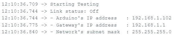
If I stack the shield on the Mega like normal:
image
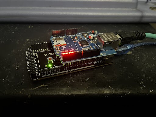
The program produces the correct info in the serial monitor:
image

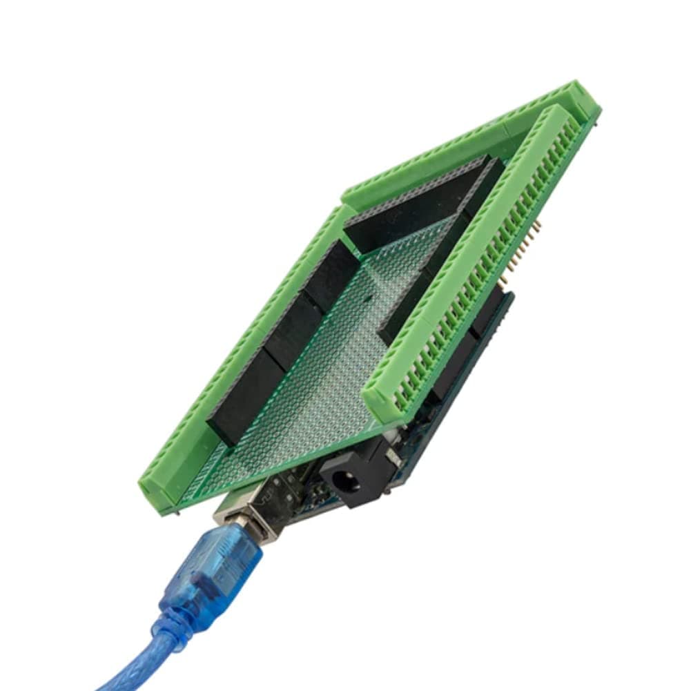
However, when I move them to the breakout boards and wire them up in the following manner, I get bogus results.
Mega screw terminals to
Uno shield screw terminals and ICSP pins
5V / GND / RST / 50....../ 51....../ 52
5V / GND / RST / MISO / MOSI / SCK
image
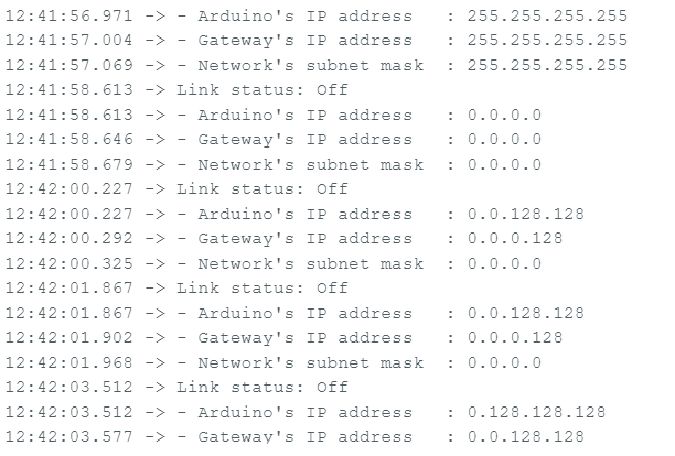
The program produces garbage like this:
image

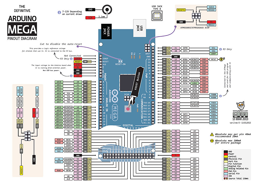
I confirmed I have the shield ICSP pins correct. In that orientation L to R, T to B the pins would be:
RST........... / GND
13(SCK).... / 11(MOSI)
12(MISO)../ 5V

I verified by confirming the RST, GND, and 5V ICSP pins all have continuity to the screw terminals for the same.

Pulling the ICSP wires will change the random garbage I get in the serial monitor. For S&G's I swapped the MISO/MISO and the SCK wires all around. All garbage combinations.
Connected 3.3V between the breakouts just to test. No change.

But, if I put the shield directly back on the Mega.... it's all ok.

What am I missing?

Screw terminals:
Have you thought of buying sensors with normal pins, then designing little adapter PCBs on to which the sensors can be soldered, as can standalone screw terminals? PCB ordering is very cheap thesedays (JLCPCB and/or PCBWAY), and there is free software like KiCAD to design them with. Consider designing something like this:
https://cpc.farnell.com/seeed-studio/103020007/grove-screw-terminal/dp/MK00578
but instead of that grove header, have pads on the PCB for whichever sensor you want to mount.

Also, just a thought, what about 38KHz IR for long range comms? Could be good so long as your data rate needed is under a few hundred bytes per second. Like used for TV remotes? You can buy IR LEDs, and you can buy receivers (TSOP38238 and such) which have internal gain controland amplifiers to give a logic level output. If you have line of sight from the control panel to the model layout this could work. I would always suggest putting a checksum byte in each IR message sent, so the receiver would ignore the message if other sources of light corrupt it, and then repeat each message sent quite a few times, so one should get through uncorrupted.

No, I don’t want to learn all the way down to board design for this. And the IR idea doesn’t address my goal.

I have bought that proto board shield to try, along with some pin extenders.
Should be able to sandwich the board between the Mega and Ethernet shield and still have screw terminal locations.
I do lose the ability to DIN rail mount it though.