Hi. When you watch a YoutUbe video, not full-screen, below the video will be a line of text introducing the video ending with a bolded "show more" link that you should click to reveal links to all their code and drawings, even links to the parts they used. Share what you find!

Here is a screen shot of your current transformer/ Arduino project. I hope you can view it. I jiust want to know where the circled wires go to/connect to. Not explained in your Youtube video and I could not pull up and see any kind of schematic in your SHOW MORE section.
Here is a nice reference for connecting your rail...
The following web site is the model railroad community... where you can find information on connecting your transformer to your rail.
That's my question. These 3 wires do they just connect to your power transformer that operates your locomotive or some thing else.
Probably not. It looks like you are trying to make the Arduino power your 12vdc ~18vdc train. That would burn your Arduino.
What is the input to your transformer?
What is the output from your transformer?
My train was powered like this:
(mains)==>>A/C==>>(xmfr)==>>12vdc==>>(tracks)
Polarity was not important for my tracks because my xmfr had a "reverse" switch.
Well from what I understand the Arduino runs on 5-7.5 Vdc which is lower than track voltage and from a different power source NOT the track transformer. I was wondering if the black wire warped around your current transformer goes to your track transformer wrapped around your current transformer then goes to your isolated rail connected to your orange wire. Now the wire connected to your rail before and after your insulated rail connector just wondering if they go back to the same transformer connection that your current transformer lead wire goes to. In other words do you have 3 wires hooked up to your track trans former on the same terminal regardless of polarity. So you can regulate the speed and direction of your locomotive. Keep in mind the Train transformer DOSE NOT power the Arduino. That is a separate lower voltage power source which I know.
Chris Z.

This guy has about 8 videos of 10 minutes on his turntable project.

Arduino Uno can use 12 Volts DC.
As I understand it you can use higher voltages with some ifs and buts - up to around 20V.
Hi.
To put it simply;
The problem is that the regulator on the controller PCB is a linear regulator.
This is not very efficient and the higher the input volts the more heat/power is dissipated in the regulator, if it gets too hot it shuts down.
Tom.. ![]()
![]()
![]()
![]()
1 Like
I’ve seen his video’s and he dose not tell or show how his components are hooked up and he dose not show or explain his code. But his box is what I want to learn to build and program code for. If you look at his part 3 video that is what I’m trying to emulate.
I will view that video series. I appreciate your interest in trains (model and real). My mother gave to me many model buildings to build, and eventually an N-scale track (small room). Later in life (decades ago) I finished her attic for living space so my father could set up his tracks. He had Z, N and HO... hills, tunnels, signals, crossings, trees, et c. I gave to him an RC mini-helicopter for his hospital. He still tinkers with it. Climbing the stairs are what keeps him from doing more.
Thank you for the encouraging info. I have several train types from G scale down to Z scale. The only one I don't have I think is T or TT scale which is American Flyer. I even have Marklin HO and Z scale.
Chris Z.
So where does it get in the inefficient range?
12 Volts?
Higher?
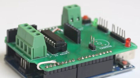
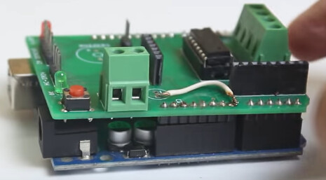
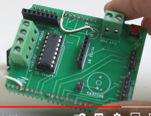
Saw a Youtube video by Mr Innovative titled 'Arduino PID based DC motor position control system'. Looking for some sort of blue tooth shield kit he purchased and built. Can't find a part or part number or US distributor to purchase this. I downloaded some photo's so hopefuly some one can recognize this and let me know what it is and where I can buy it.


At any voltage above the minimum voltage. ![]() Linear regulation is inherently lossy. An LDO (low dropout) regulator is just less lossy. But that is only because it is not challenged with a large input-output voltage differential.
Linear regulation is inherently lossy. An LDO (low dropout) regulator is just less lossy. But that is only because it is not challenged with a large input-output voltage differential.
The issue is heat generation, which is in Watts:
P = (inputV - regulatedV) x supply current
So if Vin = 12V, the differential is 6V, if the 5V has for example a 100mA load, the regulator dissipation is approximately
(12 - 5) x 0.1 = 0.6W
"Mr Innovative" provides a link to fab the PCB yourself. Probably not too many people bother, as it isn't really a great board. The motor IC is weak, and it looks like the bottom of the row of header pins is dangerously close to hitting the USB connector shield and shorting out.
This won't save you any time. It will just add headaches.
Saw a Youtube video by Mr Innovative titled 'Arduino PID based DC motor position control system'. Looking for some sort of blue tooth shield kit he purchased and built. Can't find a part or part number or US distributor to purchase this. I downloaded some photo's so hopefuly some one can recognize this and let me know what it is and where I can buy it.
What is the controller You want to use? Goggle on that board + Bluetooth shield. There are likely several ones out there.
The IC look like a 74374 or somthing, a digital circuit... Not a typical BT circuit.
It looks like an L293D H-bridge driver and a place to plug an HC-05 bluetooth breakout and an MPU-6050 breakout.
duplicate post, flagged for moderation