Hello domapi.
Thats a really nice looking project. I will certainly spend some time reading it over in more depth, but having skim read it, it is certainly a work of art. Well done!
And it uses (among others) the MobaTools library I already suggested in #13 ![]()
2 Likes
- In the previous schematic, I had the LED backwards, it is now correct.
This LED, as mentioned, toggles very 500ms, we use it to help show us if the code is stuttering or if the code has a blocking event.
It's as good as your eyes are
Test time.
- In the area above setup( ) you will find the code seen below.
//========================
makeTIMER heartbeatTIMER =
{
  MILLIS, 0, 500ul, ENABLED, YES       //.TimerType, .Time, .Interval, .TimerFlag, .Restart
};
-
The code above makes a non-blocking TIMER object called heartbeatTIMER
It is a millisecond TIMER that expires at 500ms.
At power up time this TIMER is enabled, when this TIMER expires, it automatically restarts and will expire in another 500ms.
This action happens over and over. -
Please explain what the code below does ?
//========================
makeTIMER machineTIMER =
{
  MICROS, 0, 1000ul, ENABLED, YES      //.TimerType, .Time, .Interval, .TimerFlag, .Restart
};
- The code below is found at the top of the loop( ) function.
  //========================================================================  T I M E R  heartbeat
  //condition returned: STILLtiming, EXPIRED or TIMERdisabled
  //if the TIMER is enabled, is it time to toggle the heartbeat LED ?
  if (heartbeatTIMER.checkTIMER() == EXPIRED)
  {
    //toggle the heartbeat LED
    digitalWrite(heartbeatLED, digitalRead(heartbeatLED) == HIGH ? LOW : HIGH);
  }
- Explain what the above code section does, assume we have just powered the Arduino up.
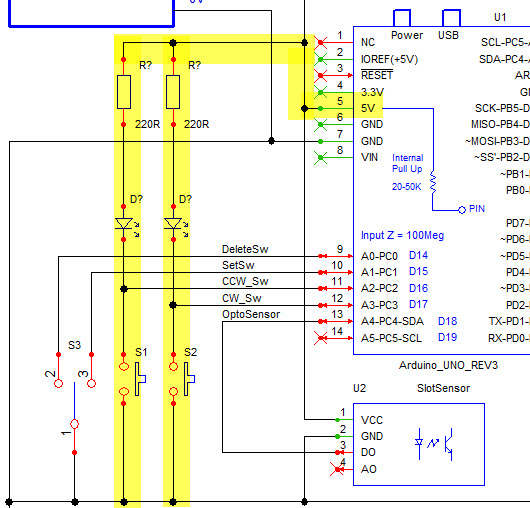
- In the schematic below, D1 and D2 can be controlled by the Arduino.
D1 turns ON when Arduino pin 8 goes LOW.
D2 turns ON when Arduino pin 7 goes HIGH. - Do you understand why D1 opposite to D2 ?

[quote="LarryD, post:83, topic:1263988"]
- Please explain what the code below does ?
//========================
makeTIMER machineTIMER =
{
  MICROS, 0, 1000ul, ENABLED, YES      //.TimerType, .Time, .Interval, .TimerFlag, .Restart
};
The makeTimer refers to the logic system that the system uses to determine what decision should be made in lines 34-164.
The Micros refers to a millionth of a second and is therefore faster and more accurate. it remains an unsigned long.
the 0 refers to the timer starting upon power up.
1000ul refers to the timer restarting every second.
ENABLED refers to the timer being active.
YES means we restart the timer at the end of the current timed period.
MachineTimer part I believe means an internal timer that allows the system to keep track of elapsed time so as to keep all other timers accurate.
The condition returned line refers to feedback from the timer that would not require an action at this time. However IF the timer is checked and found to have EXPIRED then then toggle heartbeat LED line takes affect.
The DigitalRead refers to the reading of a pins state - high or low.
DigitalWrite refers to the setting of a state to a pin.
im not sure about the ==HIGH? Low:High as ive not seen it like this before. However, usually it refers to orders of if low make high, if high make low etc.
It is my understanding that when pin D8/23 goes low it turns Diode D1 on because the flow of power can begin. In that the other side of the diode is High so by going Low it allows the flow to start. The LEDiode allows the flow in one direction only, with the line of its drawing acting effectively as a barrier. When the pin is high the power cannot flow in that direction as it is blocked. there is also the issue of the other side being already high as it is connected direct to the power supply. so the diode is used to stop a short occurring and so would only work when the pin goes low.
Diode 2 is wired so that the barrier is after the LED with the output pin D7/22 going to it. It therefore allows travel in that direction to ground only. If pin22 were low then the other side is also already low/ground. and there would be no light anyway without a power supply to it. When pin 22 goes high the LED can light because the power can then flow through the LED to ground.
- We are making a non-blocking TIMER called, machineTIMER
This is a microsecond TIMER that expires at 1000 microseconds which is 1 milliSecond.
At power up time, the TIMER is enable and when it expires, it automatically restarts timing for another 1ms, this repeats over and over. - Later in the code we will see when this TIMER expires, we call the checkMachine( ) function. i.e. we check our State Machine to see if it needs servicing.
digitalWrite(heartbeatLED, digitalRead(heartbeatLED) == HIGH ? LOW : HIGH);
digitalRead(heartbeatLED) == HIGH ? LOW : HIGH
-
This says, if the current state of the heartbeatLED is HIGH make it LOW, and if it is LOW, make it HIGH, hence toggle.
-
Google
Ternary Operator
- Correct !
![]()
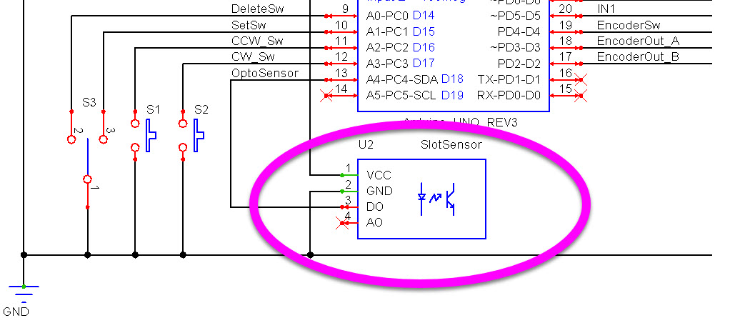
- What is the Opto Sensor for ?
That makes sense now. I hadn't seen it written in the shorthand before.
- What is the Opto Sensor for ?
- Connect the Stepping Motor as shown in the last schematic.
- Press and hold the CW switch.
- Release the CW switch and press and hold the CCW switch.
- What do you observe in the Serial Monitor and what happens with the motor shaft ?
//================================================^================================================
//
// https://forum.arduino.cc/t/model-railway-turntable-in-a-spin-so-much-im-dizzy/1263988
//
// HLD
//
// Version YY/MM/DD Comments
// ======= ======== ========================================================================
// 1.00 24/05/25 Started writing sketch
// 1.10 24/05/25 Added code to read the Rotary Encoder
// 1.20 24/05/25 Added Stepping Motor code
//
//#include <Wire.h>
// M A C R O S
//================================================^================================================
#define LEDon HIGH //PIN---[220R]---A[LED]K---GND
#define LEDoff LOW
#define PRESSED LOW //+5V---[Internal 50k]---PIN---[Switch]---GND
#define RELEASED HIGH
#define CLOSED LOW //+5V---[Internal 50k]---PIN---[Switch]---GND
#define OPENED HIGH
// G P I O s
//================================================^================================================
//
//a structure to define input objects
struct makeInput
{
const byte pin; //the digital input pin number
unsigned long switchTime; //the time the switch was closed
byte lastState; //the state the input was last in
byte counter; //a counter used to validate a switch change in state
}; //END of struct makeInput
const byte inputPins[] = {4, 14, 15, 16, 17, 18};
//Digital Inputs
//define the input connected to a PB switch
//========================
makeInput EncoderSw =
{
4, 0, OPENED, 0 //pin, switchTime, lastState, counter
};
//========================
makeInput DeleteSw =
{
14, 0, OPENED, 0 //pin, switchTime, lastState, counter
};
//========================
makeInput SetPosSw =
{
15, 0, OPENED, 0 //pin, switchTime, lastState, counter
};
//========================
makeInput CCW_Sw =
{
16, 0, OPENED, 0 //pin, switchTime, lastState, counter
};
//========================
makeInput CW_Sw =
{
17, 0, OPENED, 0 //pin, switchTime, lastState, counter
};
//========================
makeInput OptoSensor =
{
18, 0, OPENED, 0 //pin, switchTime, lastState, counter
};
byte filter = 10;
//TIMER "switches" runs every 5ms.
//5ms * 10 = 50ms is needed to validate a switch change in state.
//A switch change in state is valid "only after" 10 identical changes are detected.
//This is used to filter out EMI noise in the system
const byte EncoderOutA = 3; //there is a pull-up resistor inside the rotary encoder
const byte EncoderOutB = 2; //there is a pull-up resistor inside the rotary encoder
//OUTPUTS
//===================================
const byte outputPins[] = {13, 12, 11, 10, 9, 8, 7, 6, 5};
const byte heartbeatLED = 13;
const byte cwLED = 12;
const byte ccwLED = 11;
const byte deleteLED = 10;
const byte setPosLED = 9;
//stepping motor
const byte IN4 = 8;
const byte IN3 = 7;
const byte IN2 = 6;
const byte IN1 = 5;
//VARIABLES
//===================================
//Stepping Motor stepping pattern
//index 0 1 2 3 4 5 6 7
int lookup[8] = {B01000, B01100, B00100, B00110, B00010, B00011, B00001, B01001};
//where we are pointing to in the above array
int stepIndex = 0;
int EncoderCounter;
const int countsRerRev = 512; //steps in a full revolution
const unsigned long motorSpeed = 2400ul; //larger the number, slower the the motor movement
//================================================^================================================
// millis() / micros() B a s e d T I M E R S
//================================================^================================================
//These TIMER objects are non-blocking
struct makeTIMER
{
#define MILLIS 1
#define MICROS 1000 //we can use this value to divide into a variable to get milliseconds
#define ENABLED true
#define DISABLED false
#define YES true
#define NO false
#define STILLtiming 0
#define EXPIRED 1
#define TIMERdisabled 2
//these are the bare minimum "members" needed when defining a TIMER
int TimerType; //what kind of TIMER is this? MILLIS/MICROS
unsigned long Time; //when the TIMER started
unsigned long Interval; //delay time which we are looking for
bool TimerFlag; //is the TIMER enabled ? ENABLED/DISABLED
bool Restart; //do we restart this TIMER ? YES/NO
//================================================
//condition returned: STILLtiming (0), EXPIRED (1) or TIMERdisabled (2)
//function to check the state of our TIMER ex: if(myTimer.checkTIMER() == EXPIRED);
byte checkTIMER()
{
//========================
//is this TIMER enabled ?
if (TimerFlag == ENABLED)
{
//========================
//has this TIMER expired ?
if (getTime() - Time >= Interval)
{
//========================
//should this TIMER restart again?
if (Restart == YES)
{
//restart this TIMER
Time = getTime();
}
//this TIMER has expired
return EXPIRED;
}
//========================
else
{
//this TIMER has not expired
return STILLtiming;
}
} //END of if (TimerFlag == ENABLED)
//========================
else
{
//this TIMER is disabled
return TIMERdisabled;
}
} //END of checkTime()
//================================================
//function to enable and restart this TIMER ex: myTimer.enableRestartTIMER();
void enableRestartTIMER()
{
TimerFlag = ENABLED;
//restart this TIMER
Time = getTime();
} //END of enableRestartTIMER()
//================================================
//function to disable this TIMER ex: myTimer.disableTIMER();
void disableTIMER()
{
TimerFlag = DISABLED;
} //END of disableTIMER()
//================================================
//function to restart this TIMER ex: myTimer.restartTIMER();
void restartTIMER()
{
Time = getTime();
} //END of restartTIMER()
//================================================
//function to force this TIMER to expire ex: myTimer.expireTimer();
void expireTimer()
{
//force this TIMER to expire
Time = getTime() - Interval;
} //END of expireTimer()
//================================================
//function to set the Interval for this TIMER ex: myTimer.setInterval(100);
void setInterval(unsigned long value)
{
//set the Interval
Interval = value;
} //END of setInterval()
//================================================
//function to return the current time
unsigned long getTime()
{
//return the time i.e. millis() or micros()
//========================
if (TimerType == MILLIS)
{
return millis();
}
//========================
else
{
return micros();
}
} //END of getTime()
}; //END of struct makeTIMER
// D e f i n e a l l a r e T I M E R S
//================================================^================================================
/*example
//========================
makeTIMER toggleLED =
{
MILLIS/MICROS, 0, 500ul, ENABLED/DISABLED, YES/NO //.TimerType, .Time, .Interval, .TimerFlag, .Restart
};
Function we can access to:
toggleLED.checkTIMER();
toggleLED.enableRestartTIMER();
toggleLED.disableTIMER();
toggleLED.expireTimer();
toggleLED.setInterval(100ul);
*/
//========================
makeTIMER heartbeatTIMER =
{
MILLIS, 0, 500ul, ENABLED, YES //.TimerType, .Time, .Interval, .TimerFlag, .Restart
};
//========================
makeTIMER switchesTIMER =
{
MILLIS, 0, 5ul, ENABLED, YES //.TimerType, .Time, .Interval, .TimerFlag, .Restart
};
//========================
makeTIMER encoderTIMER =
{
MILLIS, 0, 2ul, ENABLED, YES //.TimerType, .Time, .Interval, .TimerFlag, .Restart
};
//========================
makeTIMER machineTIMER =
{
MICROS, 0, 1000ul, ENABLED, YES //.TimerType, .Time, .Interval, .TimerFlag, .Restart
};
//========================
makeTIMER commonTIMER =
{
MILLIS, 0, 1000ul, DISABLED, NO //.TimerType, .Time, .Interval, .TimerFlag, .Restart
};
//========================
makeTIMER stepperTIMER =
{
MICROS, 0, motorSpeed, DISABLED, YES //.TimerType, .Time, .Interval, .TimerFlag, .Restart
};
// S t a t e M a c h i n e
//================================================^================================================
//the States in our machine (use better names that mean something to you)
enum STATES : byte
{
STARTUP, STATE1, STATE2, STATE3, STATE4, FINISHED
};
STATES mState = STARTUP;
// s e t u p ( )
//================================================^================================================
void setup()
{
Serial.begin(115200);
//======================
//use INPUT_PULLUP so the pin does not float, floating pins can cause faulty readings
//configure the input pins
for (byte x = 0; x < sizeof(inputPins); x++)
{
pinMode(inputPins[x], INPUT_PULLUP);
}
//======================
//configure the output pins
for (byte x = 0; x < sizeof(outputPins); x++)
{
digitalWrite(outputPins[x], LOW);
pinMode(outputPins[x], OUTPUT);
}
} //END of setup()
// l o o p ( )
//================================================^================================================
void loop()
{
  //========================================================================  T I M E R  heartbeat
  //condition returned: STILLtiming, EXPIRED or TIMERdisabled
  //if the TIMER is enabled, is it time to toggle the heartbeat LED ?
  if (heartbeatTIMER.checkTIMER() == EXPIRED)
  {
    //toggle the heartbeat LED
    digitalWrite(heartbeatLED, digitalRead(heartbeatLED) == HIGH ? LOW : HIGH);
  }
//======================================================================== T I M E R switches
//if the TIMER is enabled, is it time to check our switches ?
if (switchesTIMER.checkTIMER() == EXPIRED)
{
checkSwitches();
}
//======================================================================== T I M E R encoder
//if the TIMER is enabled, is it time to read the Rotary Encoder ?
if (encoderTIMER.checkTIMER() == EXPIRED)
{
readRotaryEncoder();
}
//======================================================================== T I M E R machine
//if the TIMER is enabled, is it time to service our State Machine ?
if (machineTIMER.checkTIMER() == EXPIRED)
{
checkMachine();
}
  //========================================================================  T I M E R  stepper
  //if the TIMER is enabled, is it time to move the Stepping Motor ?
  if (stepperTIMER.checkTIMER() == EXPIRED)
  {
    //========================
    //when the CW switch is closed
    if (CW_Sw.lastState == CLOSED)
    {
      //move the stepper
      stepMotor(stepIndex);

      //get ready for the next step
      stepIndex++;

      //should we go back to the beginning index ?
      if (stepIndex > 7)
      {
        stepIndex = 0;
      }
    }

    //========================
    //when the CCW switch is closed
    else if (CCW_Sw.lastState == CLOSED)
    {
      //move the stepper
      stepMotor(stepIndex);

      //get ready for the next step
      stepIndex--;

      //should we go back to the ending index ?
      if (stepIndex < 0)
      {
        stepIndex = 7;
      }
    }
  }
//================================================
//other non blocking code goes here
//================================================
} //END of loop()
// c h e c k M a c h i n e ( )
//================================================^================================================
void checkMachine()
{
//================================================
//service the current "state"
switch (mState)
{
//========================
case STARTUP:
{
//do startup stuff
}
break;
//========================
case STATE1:
{
//Do Something
}
break;
//========================
case STATE2:
{
//Do something
}
break;
//========================
case STATE3:
{
//Do something
}
break;
//========================
case STATE4:
{
//Do something
}
break;
//========================
case FINISHED:
{
//Do something
}
break;
} //END of switch/case
} //END of checkMachine()
// c h e c k S w i t c h e s ( )
//================================================^================================================
void checkSwitches()
{
byte currentState;
//======================================================================== EncoderSw.pin
currentState = digitalRead(EncoderSw.pin);
//===================================
//has this switch changed state ?
if (EncoderSw.lastState != currentState)
{
EncoderSw.counter++;
//is this change in state stable ?
if (EncoderSw.counter >= filter)
{
//get ready for the next sequence
EncoderSw.counter = 0;
//update to this new state
EncoderSw.lastState = currentState;
//========================
//did this switch close ?
if (currentState == CLOSED)
{
//reset the Encoder Counter
EncoderCounter = 0;
Serial.print("Encoder Counter = ");
Serial.println(EncoderCounter);
//the time this switch closed
EncoderSw.switchTime = millis();
}
//========================
//did this switch open ?
else if (currentState == OPENED)
{
Serial.print("The time the switch was closed = ");
Serial.println(millis() - EncoderSw.switchTime);
}
}
}
//===================================
//a valid switch change has not been confirmed
else
{
EncoderSw.counter = 0;
}
//END of EncoderSw.pin
//======================================================================== CW_Sw.pin
//only proceed if the CCW switch is OPEN
if (CCW_Sw.lastState == OPENED)
{
currentState = digitalRead(CW_Sw.pin);
//===================================
//has this switch changed state ?
if (CW_Sw.lastState != currentState)
{
CW_Sw.counter++;
//is this change in state stable ?
if (CW_Sw.counter >= filter)
{
//get ready for the next sequence
CW_Sw.counter = 0;
//update to this new state
CW_Sw.lastState = currentState;
//========================
//did this switch close ?
if (currentState == CLOSED)
{
Serial.println("Motor going Clockwise");
//movement is now allowed and the Motor will move CW
stepperTIMER.enableRestartTIMER();
digitalWrite(cwLED, LEDon);
}
//========================
//did this switch open ?
else if (currentState == OPENED)
{
Serial.println("Motor Stopped");
//movement is now disabled and the Motor will stop
stepperTIMER.disableTIMER();
digitalWrite(cwLED, LEDoff);
}
}
}
}
//===================================
//a valid switch change has not been confirmed
else
{
CW_Sw.counter = 0;
}
//END of CW_Sw.pin
//======================================================================== CCW_Sw.pin
//only proceed if the CW switch is OPEN
if (CW_Sw.lastState == OPENED)
{
currentState = digitalRead(CCW_Sw.pin);
//===================================
//has this switch changed state ?
if (CCW_Sw.lastState != currentState)
{
CCW_Sw.counter++;
//is this change in state stable ?
if (CCW_Sw.counter >= filter)
{
//get ready for the next sequence
CCW_Sw.counter = 0;
//update to this new state
CCW_Sw.lastState = currentState;
//========================
//did this switch close ?
if (currentState == CLOSED)
{
Serial.println("Motor going Counter Clockwise");
//movement is now allowed and the Motor will move CCW
stepperTIMER.enableRestartTIMER();
digitalWrite(ccwLED, LEDon);
}
//========================
//did this switch open ?
else if (currentState == OPENED)
{
Serial.println("Motor Stopped");
//movement is now disabled and the Motor will stop
stepperTIMER.disableTIMER();
digitalWrite(ccwLED, LEDoff);
}
}
}
}
//===================================
//a valid switch change has not been confirmed
else
{
CCW_Sw.counter = 0;
}
//END of CCW_Sw.pin
//======================================================================== DeleteSw.pin
currentState = digitalRead(DeleteSw.pin);
//===================================
//has this switch changed state ?
if (DeleteSw.lastState != currentState)
{
DeleteSw.counter++;
//is this change in state stable ?
if (DeleteSw.counter >= filter)
{
//get ready for the next sequence
DeleteSw.counter = 0;
//update to this new state
DeleteSw.lastState = currentState;
//========================
//did this switch close ?
if (currentState == CLOSED)
{
Serial.println("Delete switch closed");
//toggle LED
digitalWrite(deleteLED, digitalRead(deleteLED) == HIGH ? LOW : HIGH);
}
//========================
//did this switch open ?
else if (currentState == OPENED)
{
Serial.println("Delete switch opened");
}
}
}
//===================================
//a valid switch change has not been confirmed
else
{
DeleteSw.counter = 0;
}
//END of DeleteSw.pin
//======================================================================== SetPosSw.pin
currentState = digitalRead(SetPosSw.pin);
//===================================
//has this switch changed state ?
if (SetPosSw.lastState != currentState)
{
SetPosSw.counter++;
//is this change in state stable ?
if (SetPosSw.counter >= filter)
{
//get ready for the next sequence
SetPosSw.counter = 0;
//update to this new state
SetPosSw.lastState = currentState;
//========================
//did this switch close ?
if (currentState == CLOSED)
{
Serial.println("Set switch closed");
//toggle LED
digitalWrite(setPosLED, digitalRead(setPosLED) == HIGH ? LOW : HIGH);
}
//========================
//did this switch open ?
else if (currentState == OPENED)
{
Serial.println("Set switch opened");
}
}
}
//===================================
//a valid switch change has not been confirmed
else
{
SetPosSw.counter = 0;
}
//END of SetPosSw.pin
} //END of checkSwitches()
// r e a d R o t a r y E n c o d e r ( )
//================================================^================================================
void readRotaryEncoder()
{
static byte lastStateA = digitalRead(EncoderOutA);
byte currentStateA;
currentStateA = digitalRead(EncoderOutA);
//=========================================
//has this state changed ?
if (lastStateA != currentStateA)
{
//update to the new state
lastStateA = currentStateA;
//========================
//when the outputB state is different from the outputA state,
//we are rotating clockwise CW
if (digitalRead(EncoderOutB) != currentStateA)
{
//CW
EncoderCounter++;
}
//========================
//we are rotating counter clock wise CCW
else
{
//CCW
EncoderCounter--;
}
Serial.print("Encoder Counter = ");
Serial.println(EncoderCounter);
}
} //END of readRotaryEncoder()
// s t e p M o t o r ( )
//================================================^================================================
void stepMotor(int output)
{
digitalWrite(IN1, bitRead(lookup[output], 0));
digitalWrite(IN2, bitRead(lookup[output], 1));
digitalWrite(IN3, bitRead(lookup[output], 2));
digitalWrite(IN4, bitRead(lookup[output], 3));
} //END of setpMotor()
//================================================^================================================
- Explain what the following code does ?
//======================================================================== T I M E R stepper
//if the TIMER is enabled, is it time to move the Stepping Motor ?
if (stepperTIMER.checkTIMER() == EXPIRED)
{
//========================
//when the CW switch is closed
if (CW_Sw.lastState == CLOSED)
{
//move the stepper
stepMotor(stepIndex);
//get ready for the next step
stepIndex++;
//should we go back to the beginning index ?
if (stepIndex > 7)
{
stepIndex = 0;
}
}
//========================
//when the CCW switch is closed
else if (CCW_Sw.lastState == CLOSED)
{
//move the stepper
stepMotor(stepIndex);
//get ready for the next step
stepIndex--;
//should we go back to the ending index ?
if (stepIndex < 0)
{
stepIndex = 7;
}
}
}
The schematic in post 83 has no opto sensor so i presume we are back to the edited schematic of my own project.
I can see on line 266 that we have made it an input and assigned the correct pin to it.
makeInput OptoSensor =
{
  18, 0, OPENED, 0                        //pin, switchTime, lastState, counter
};
So we are setting pin 18, it becomes active as soon as the system powers and its normal state is open i.e. unbroken.
I cannot find anywhere that it actually is told to do anything with the information yet.
This also ring true with my real world setup as nothing occurs and the serial monitor does not record anything either.
So pressing the button briefly makes the motor turn a step. Hold it moves multiple steps until released.
I had to check my wiring against the schematic here though as when i pressed the CW button it moved CCW but the serial monitor reported CW.
vice versa with the CCW switch.
I therefore wasn't sure if i had wired them round the wrong way but im pretty sure i have then correct.
The serial monitor reports motor is moving when button is held/pressed and Motor stopped when the button is released.
- And what do the CW and CCW LEDs do when the CW and CCW switches are closed ?
- If the CW and CCW LEDs only monitor the CW and CCW switches then wiring the LEDs here would do the same thing, no need to waste two GPIOs.
Sorry. I will need it for setting the zero point on the turntable itself. That way if the previous location isn't saved to the EEPROM then the system can initialise a find zero routine so reestablish/calibrate.
- To detect the zero position, a simple micro switch would be simpler
 .
.

my only thinking behind it was that I wanted to leave the LED lit whilst the action of moving to the next stored location was carried out by the motor. I was also hoping to make the led flash or indicate to the user in some way that it was carrying out a half turn routine. and/or flash both together if the zero routine was being carried out.
- Okay.
I thought that too but ive not been able to find one small enough.
Because the table can turn both ways the switch needs to accept something from both directions that triggers it. i therefore felt i needed one with a wheel on the end of it. rather than the n shape on this one.
But i am open to doing it this way if it would save a lot of time and effort, and prove more reliable/accurate. I can use the ones i bought for testing and then try and locate a smaller one for the real thing.
Like i said before, the size of this scale is extremely limiting and creates problems within itself.