sorry for the confusion i am not that good at explaining things but we are all on the same page now
thejmr:
sorry for the confusion i am not that good at explaining things but we are all on the same page now
Are all your problems solved now, or do you still have some questions?
...R
raschemmel:
Wouldn't it have made more sense to call them START button and DESTINATION-5 button ?or
Destination-1 button and Destination-5 button
And if you want to drive a train in the opposite direction your START button becomes your DESTINATION button!
Do you work for Microsoft, the people that decided it would be a good idea to put SHUTDOWN on the START button?
thejmr:
sorry for the confusion i am not that good at explaining things but we are all on the same page now
My recommendation is that you put a clearly labelled CANCEL button on your control panel, for when you accidentally hit the wrong route button. ![]()
And if you want to drive a train in the opposite direction your START button becomes your DESTINATION button!
Do you work for Microsoft, the people that decided it would be a good idea to put SHUTDOWN on the START button?
Oh come on. Does nobody else think "button-1" and "button -5 " are unimaginative and useless names for these buttons ?
raschemmel:
Oh come on. Does nobody else think "button-1" and "button -5 " are unimaginative and useless names for these buttons ?
For all we know the actual buttons on the control panel may be numbered 1, 2, 3 etc.
...R
raschemmel:
Oh come on. Does nobody else think "button-1" and "button -5 " are unimaginative and useless names for these buttons ?
Yes, probably should be "Fred", "Nancy", "George" etc.
ok We shall start a Fresh guys.
Project
To create a Route Setting system same as in a Modern Signal box
Issue
I have no idea how to start the code.
Concept Explained
every route is controlled by passage of trains and routes defined by the signal man
Routes are defined by the pressing of Buttons, 1 button to start to route and 2nd to define end.
When the route is selected it works out If the track is Occupied If Not it switches the Points to make the route
When the points are in the correct position it releases the Signal to display Green. .
IF a Platform or Siding
It uses a procedure that is Call "CALL ON" this allows the points and signal to control the speed of a train because there is another train on that platform or siding already.
What I have.
I have a way of signal control with a GND and input on the Signal.
Occupicy dector to tell if the track is Free or taken.
Relay to switch the points
Points Motors
What I Need
I have No idea where to start with the code.
Ardunio needs to remember the state of buttons eg needs to remember what button was pressed 1st and then 2nd.
Then it needs to work out what relays it needs to switch on and off Momentary to throw the points.
I was orgnially going to have LCD. This is going to be scrapped for LEDS showing the route I can manage that bit
I am struggling with the base of the code the buttons and switching of points command.
I have got an arduino MEGA in the post but as a Demo I am going to be using a UNO once got the code I shall move on to the Mega to complete the code.
Hope this makes more sense.
Jordan
Can you model it on how real trains work?
thejmr:
Issue
I have no idea how to start the code.
Forget about code for a few days. The more thinking and planning you do the easier the code will be when you get to that stage.
It seemed to me that your earlier diagram was just a fragment. If you have a full trackplan and know where all the route selection buttons will go post a copy of it - but keep the size to 1280 x 960 or smaller. If you don't have a full trackplan put together a simple but complete plan that encompasses all the situations you want to allow for.
The purpose of this is so that people here have the same reference "document" as you have. It will make discussion enormously easier.
In parallel with producing the track plan you can be thinking about making a list of all the valid routes.
...R
Online Plan
http://thejmr.info/wp-content/uploads/2014/10/StoneHall.jpg
Numbered and Labled
http://thejmr.info/wp-content/uploads/2014/10/bed-room-layout.jpg
Different colours are Different sections.
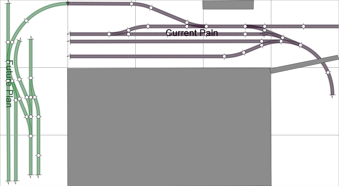
That diagram represents a lot of progress. However I can't clearly read the numbers - perhaps you do a clearer version.
Also, and perhaps more important, there are a lot of white spots with no numbers.
Maybe your numbers are just identifying the points / turnouts? If so each one will have 2 options.
Can you give me a couple of examples of how you would like to set routes for these moves
-
Clockwise from the future plan all the way round to the fiddleyard non-stop
-
Counter-Clockwise from the fiddle yard to the straight purple section between 3 and 6
And if you give some more examples that would be even better.
...R
Thank you for the reply
For now we will just settle with it switching points for routes.
I have now written on the Plan hopeful either will confuse things or make it clearer.
Each section has a button.
So
If I wanted a train to go from the Fiddle Yard to the Platform 1
I would press the button in the Fiddle Yard and then the one on Platform 1.
Arduino would switch the points and clear the route.
and so on so If I wanted to go from Section 9 to the Fiddle yard.
I would Press the button in Section 9 and then the Fiddle Yard again
Arduino would switch the points and Clear the route.
again
If I wanted to go from the goods line to the headshunt and then to the Fiddle Yard.
I would press the button for the Goods Line and then the head shunt . the points would switch Ill move the train. Once in the headshunt . ill then select the button for the headshunt and then the button for the fiddle yard.The points would switch. ...
Hope this makes it clearer. ![]()

If you want to drive your train from the fiddle yard to the headshunt, there are two possible routes. Just pressing the buttons for section 1 and section 8 won't determine which route it should take. You'll need to press at least one more button for that.
Hi,
I just finished "marshalling yard " track routing - only the basic - one track to four - uses two switching levels.
It should be extendable to more tracks. It works on simple "algorithm" - a switch / points has an input track and two output tracks. It simply matches the desired track to a switch / points with correct output track on the highest level and than does same on next level. Basically works "backwards" from the desired track to the entry track.
Been looking at your layout and will try more complex routing next.
Cheers Vaclav
thejmr:
Thank you for the reply
For now we will just settle with it switching points for routes.
Thanks. That has made things much clearer.
I think if I was doing this project I would now need to write down a list of every route I want to use
For each route I would need the following data
- all of the train detectors that will enable that route to be confirmed clear
- the point settings needed
- the switches needed.
You can probably write them out in a grid - maybe in a spreadsheet.
The purpose of this is so that there can be lists (which will probably go into a 2D array) of the things the Arduino needs to check, and the things it needs to set
Think of the logic like this
for every detector on the route
is the detector showing clear
for every point on the route
set the point to the correct direction
...R
Here is what used for the yard routing , there are few things to be added like sensors , track priority etc.
Basically it associates each switch / points with track in two dimensional "level" array .
/*
 left - normal / straight
 right - turn  / reverse

 track#4    track#5  track#6 track#7  - level / row
 switch #2               switch #3
 track#2        track#3                     -  level / row
 switch #1
 main track #1                                -  level / row

  // initialize Switching route array
  SwitchingRoute[0][0]= 2;    //normal
  SwitchingRoute[0][1]= 3;    //reverse
  SwitchingRoute[0][2]= 1;    // input track
  SwitchingRoute[0][3]= 1;    // switch

  SwitchingRoute[1][0]= 4;//normal
  SwitchingRoute[1][1]= 5;//reverse
  SwitchingRoute[1][2]= 2;    // input track
  SwitchingRoute[1][3]= 2;    // switch

  SwitchingRoute[2][0] = 6;//normal
  SwitchingRoute[2][1] = 7;//reverse
  SwitchingRoute[2][2] = 3;    // input track
  SwitchingRoute[2][3] = 3;    // switch


 */
Thank you again for your response. The code you posted has completely Lost me but we defintly got the idea of what I wanna do I
Vaclav:
Here is what used for the yard routing , there are few things to be added like sensors , track priority etc.
Basically it associates each switch / points with track in two dimensional "level" array ./*
left - normal / straight
right - turn / reverse
track#4 track#5 track#6 track#7 - level / row
switch #2 switch #3
track#2 track#3 - level / row
switch #1
main track #1 - level / row
// initialize Switching route array
SwitchingRoute[0][0]= 2; //normal
SwitchingRoute[0][1]= 3; //reverse
SwitchingRoute[0][2]= 1; // input track
SwitchingRoute[0][3]= 1; // switch
SwitchingRoute[1][0]= 4;//normal
SwitchingRoute[1][1]= 5;//reverse
SwitchingRoute[1][2]= 2; // input track
SwitchingRoute[1][3]= 2; // switch
SwitchingRoute[2][0] = 6;//normal
SwitchingRoute[2][1] = 7;//reverse
SwitchingRoute[2][2] = 3; // input track
SwitchingRoute[2][3] = 3; // switch
*/
I am a little new and dumb at the moment to this I tend just to play around look on google until it works so can explain as your talking to an idiot. I know everything there is to know on trains and model railways but dumb to a prokject like this
thejmr:
Thank you again for your response. The code you posted has completely Lost me but we defintly got the idea of what I wanna do I
I am a little new and dumb at the moment to this I tend just to play around look on google until it works so can explain as your talking to an idiot. I know everything there is to know on trains and model railways but dumb to a prokject like this
Start by drawing up a table (in a spreadsheet would be easiest, but pen and paper will do) with the rows being the possible start positions and the columns being the possible end positions. Each cell will then contain: 1) the sections you need to check are clear before setting the points , and: 2) the points you need to set for that route and whether to normal or reverse. Obviously, where a column/row (route) combination isn't possible the cell will be left blank.
Assume that you need to move every point on the route. There's no harm in trying to move a point to the way it's already set, nothing will happen. That way, you'll not need to remember (store in memory) the current point settings.
Once you've done that, get back to us with a picture/screen capture of your table.
Henry_Best:
Start by drawing up a table (in a spreadsheet would be easiest, but pen and paper will do) with the rows being the possible start positions and the columns being the possible end positions.
As recommended in Reply #35
We are probably not both wrong !
...R