Controlling Model Train - Track Warrants

I've read several threads about controlling model trains and signaling, but nothing on Track Warrants. I'll start by saying that I don't want to have a computer hanging on my layout.

On the real thing, a central dispatcher gives a train crew a track warrant, which is an order to move from place to place. In addition to issuing the track warrant, the central dispatcher aligns the turnouts and sets the signal...and keep other traffic out of the way.

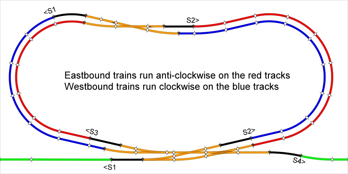
On this model train example, there are 3 pairs of red/blue tracks, where trains can pass or overtake, connected together by 2 single track mainlines. The layout contains 6 red/green signals (S1-S6), 6 un-powered blocking tracks, 8 turnouts (T1-T8), 12 electrically isolated blocks with occupancy detectors (B1-B12). The only requirement is a train must completely fit on a blue or red track.

I will use DCC to control the locomotives. If the trains have engineers with their hands on the throttle, I expect them to stop short of a red signal...and proceed through a green signal. If the trains are running un-attended, I will set them to run at different speeds and let them go. They will all run through a red signal and stop on the un-powered blocking track. A DCC controller talks to the locomotive quite often...so the locomotive will start up after track power is connected to the blocking track.

I assume that the Arduino can read each block detector. align each turnout, set the signals red or green and connect or disconnect track power from the black, blocking tracks. I'm sure some sort of proto shield will be required. The program will loop through all red and blue tracks, looking for a train to move. The table of movement looks something like this. The shorthand description of the first line is

The train on B1 can move to B6, when B3, B5 and B6 or not occupied (open) and the signals S2 and S3 are blocking traffic.

B1 > B6 when B3, B4, B5 and B6 are open and S2 and S3 are red
B2 > B6 when B3, B4, B5 and B6 are open and S1 and S3 are red
B6 > B11 when B8, B9 and B11 are open and S5 and S6 are red
B6 > B12 when B8, B9 and B12 are open and S5 and S6 are red
B11 > B7 when B7, B8, B9 and B10 are open and S5 and S4 are red
B12 > B7 when B7, B8, B9 and B10 are open and S6 and S4 are red
B7 > B1 when B1, B4 and B5 are open and S1 and S2 are red
B7 > B2 when B2, B4 and B5 are open and S1 and S2 are red

When it's time for our train on B1 to move, the turnouts T1, T3 and T4 are aligned, the signal S1 is set green, and track power is connected to the black blocking track. The first time the program looks at B1 and it's not occupied, track power is removed from the black, blocking track and the signal S1 is set red.

Other signals will be controlled by a GreenSteam GSP-14 Signal Controller By the way, this document begins with a nice dissertation on railroad signals.

Bhuck

What help do you want from us?

Weedpharma

I have no particular needs at this time. The topic has come up several times in this forum, and I hoped to advance the subject.

Bhuck

Are you automating your train layout ? If so , I would suggest it would be faster to use barcodes for the track warrants and scan them and let the arduino handle the logic to figure out what to do. I have no idea how you would do error checking to prevent scanning the wrong warrant at the wrong time. Maybe you would know.

Actually, what I automated was the central dispatcher's job. He controls the movement of all the trains. The dispatcher does that by creating a track warrant and sending it to the engineer running the train. Track warrants are also called train orders. On my model train layout, the track warrant is a green signal in front of my train.

I don't understand the speed issue. Its not a big deal if a train stops for a few extra seconds behind a red signal.

I don't understand why I need a bar code. All the decisions are based on the state of just 12 digital inputs (connected to the block occupancy detectors) plus the state of the 8 turnouts and the 6 signals.

I've attached an image of a more complex middle section with 2 pairs of red/blue sidings, which cross each other. Eastbound and Westbound trains pass each other here.

Bhuck

I haven't read your thread really carefully but I think I have the general idea.

It's not clear to me what role you plan for an Arduino (or whatever) in relation to the "thing" you call a warrant. Assuming you have an Arduino system that can control points (turnouts) and signals to set a route and can detect where a train is - where does the warrant come into the Arduino picture?

Why do you object to having a PC "hanging on your layout" ? PCs are fun - especially in conjunction with an Arduino.

...R

Trains don't move without a track warrant, issued by the dispatcher. Until recently, a track warrant was a piece of paper with hand written instructions telling the train crew how to get from here to there.

WIKI Track Warrants

When moving from here to there, a train crew must also obey the signals. I choose to model rural America with very few signals. Every railroad has their own signal chart...and a book to go with it.

Railroad Signal Charts

Guess you already have it all worked out.

@Robin2

I forgot to answer your question "Whats the purpose of the Arduino?" Assume there are 4 trains with 4 train operators playing on my example layout. The Arduino will keep them from running into each other on the mainline.

@raschemmmel

As a stated earlier, I just wanted to make some advancements on the subject. To completely automate the system, would probably require running the layout from a computer. Which I reject for personal reasons. My first computer was an HP 21MX Ancient history that still clouds my thinking.

bhuck:
The Arduino will keep them from running into each other on the mainline.

I understand the concept but it is not clear how you plan to do this.

One way is for the Arduino to control the points and signals and to issue instructions to the human operating a DCC controller. Said human is then expected to obey the signals like a real train driver.

Another way is for the Arduino to do all that and to prevent the trains from running when/where they are not supposed to.

There is also the somewhat more complex issue of managing points and signals to allow movement of multiple trains through a single junction.

My own approach to this would be to confine the Arduino to physical tasks such as moving points or signals and detecting trains and then to do the more complex logic of what should go where and when in a program on my PC.

...R

@Robin2

You are correct. The Arduino controls signals, points and blocking track power. The engineer looks at the signals, stopping when red and proceeding when green. The un-powered blocking tracks are insurance in case the engineer runs through a red signal. And, the Arduino logic only allows one train at a time on the mainline, B5 or B8.

Unless you are convinced that the Arduino can not perform the logic, I will stay with an imbedded system.

The number of inputs and outputs leads me to an Arduino Mega 2650 with a proto, screw shield that is large enough for the relays and differential drivers.

This is what I need...it will change for others.

12 x NCE BD20 DCC Occupancy Detectors connected to 12 Arduino digital inputs, defined INPUT_PULLUP

8 x Kemet EC2-5NU, DPDT Dual Coil, Latching Relays connected to 16 Arduino digital outputs, to apply and take away track power to the 8 blocking tracks

4 x TI DS1692 Dual Differential Drivers connected to 16 Arduino digital outputs to control the 8 Rokuhan turnouts. This part is obsolete, but can be had, if you know where to look.

6 x 5V red/green LED signals (of my own design) connected to 12 Arduino digital outputs

Bhuck

bhuck:
Unless you are convinced that the Arduino can not perform the logic, I will stay with an imbedded system.

I don't have a view on this because I'm still not clear what the Arduino program might look like. Perhaps you can describe a part of it - just at a high level in plain language, not in computer code. Even if the logic can be done on the Arduino a PC gives you a lot more flexibility if you want / need to make changes.

How will the Arduino prevent two trains from occupying one track if the drivers are not vigilant? When will it make the decision?

Have you considered using small servos for moving turnouts. They are very easy to control with an Arduino.

If you have dead sections of track won't the DCC chips in the locos reset - but perhaps you don't have sound and that does not matter.

What is the penalty for a driver that passes a signal at danger :slight_smile:

...R

@Robin2

When the signal goes red, track power is removed from the blocking track. An engineer can't accidentally run onto the mainline.

When power is removed from a DCC locomotive, it loses it's mind. However, the DCC command system is constantly sending messages to all the locomotive. When the signal goes green, track power is re-connected to the blocking track...and a short time later, the locomotive starts up, as if nothing has happened.

Bhuck

bhuck:
As a stated earlier, I just wanted to make some advancements on the subject. To completely automate the system, would probably require running the layout from a computer. Which I reject for personal reasons. My first computer was an HP 21MX Ancient history that still clouds my thinking.

A 328P board with SD card is probably enough computer.

But that doesn't address user I/O, which honestly could get very creative and interesting.
Like maybe use old style X in the box or punch cards for track warrants.

If you want more RAM, a 40-pin ATmega1284P chip has 16K.

If you want more pins then you can hang cheap shift registers or less cheap port expanders on the board. And by more pins, I mean literally 100's if you want. You change outputs by feeding them all a string of serial bits and then close the latch and bingo they change. You could be running all those devices you listed from an UNO.

But hey, what you've already got sounds great!
You don't get trains running through red though?

If the model train could have a controller, it could sense the red light (or ultrasonic or magnetic signal) and stop itself. It could maybe carry the track warrant if the system cooperated. maybe that would be next level in physical model simulations.

PS I should mention that the program space of AVR's can hold tables and constants as well as code. Usually many K bytes go wasted.

bhuck:
@Robin2

When the signal goes red, track power is removed from the blocking track. An engineer can't accidentally run onto the mainline.

This deals with my second question. But my first question in Reply #11 was the important one.
My concern is that you have a clear picture of the electrical issues but not of the logic issues.

...R

@Robin2

There are 6 code sections. Each code section is looking for a train on B1, B2, B6, B7, B11, B12. Here is the code section looking for a train on B1. The blocking track associated with B1 is called BT1.

Assume all the signals are red (therefore all the blocking tracks are dead)...and a train will arrive on B1...soon.

IF block B1 is NOT occupied THEN
set S1 red
remove track power from BT1
ELSE IF block B1 IS occupied THEN
IF blocks B3 and B4 and B5 are NOT occupied THEN (the mainline is open)
IF block B6 is NOT occupied THEN (the destination track is open)
IF signals S1 and S2 and S3 ARE red THEN (no trains have permission to use the mainline)
align turnouts T1 and T3 and T4
connect track power to BT1
set signal S1 green (granting permission to use the mainline)
END IF
END IF
END IF
END IF

bhuck:
There are 6 code sections. .......

That seems quite clear.

I presume the signals S1, S2 and S3 will be set by some of the other 6 code sections.

Am I correct to think that a train can only move from one section to the next and cannot run unhindered through 2 or 3 sections (assuming the tracks are available, of course).

Is there a risk of a deadlock where all 6 sections need one of the others to do something? This may be just a theoretical risk unless there are 6 trains moving (or available to move).

What you have proposed should be easy to program in an Arduino. I think I would create some 6 element arrays to hold the section data. If you know how to create and use a struct that would be even neater.

...R

There always has to be an open siding, so this scheme can manage between 1 and 5 trains. Got more trains...add more sidings to a section...or add more sections connected by more mainlines.

BTW, it also works in a circlular layout instead of a point to point layout.

When 1 train is on the layout, it will never be blocked and should never stop.
When 5 trains are on the layout, 4 will be blocked and only 1 will move.
When 2 to 4 trains are on the layout is when it gets exciting.

The code section for B5 and B6 will be a little different. I will randomly choose the destination...if they are both tracks are open.

If both B1 and B2 (also B11 and B12) are occupied, I will randomly pick the train to move first. That should make the race car drivers mad.

And finally, after looking at my code outline, blocks B3, B4 and B5 as well as B8, B9 and B10 can be combined into 2 blocks, named MainlineWest and MainlineEast, Saving the cost of 4 occupancy detectors is always good.

bhuck:
When 2 to 4 trains are on the layout is when it gets exciting.

Somebody with better maths than me would probably be able to analyze the whole system. I would build something, see how it behaves and expect to have to improve it.

...R

I wish to thank everybody, especially Robin2, for helping me get to this far.

Bhuck