@Monsters-Alive
Hey sorry I couldnt figure out the new arduino forum layout and was trying to figure out pictures.. I ended up editing the first post while you commented.
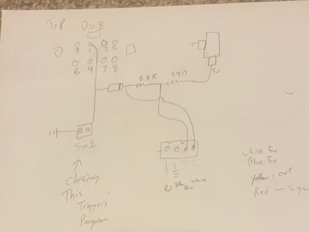
I don't quite get it. Could use pen and paper and make schematics how You wired Your setup?
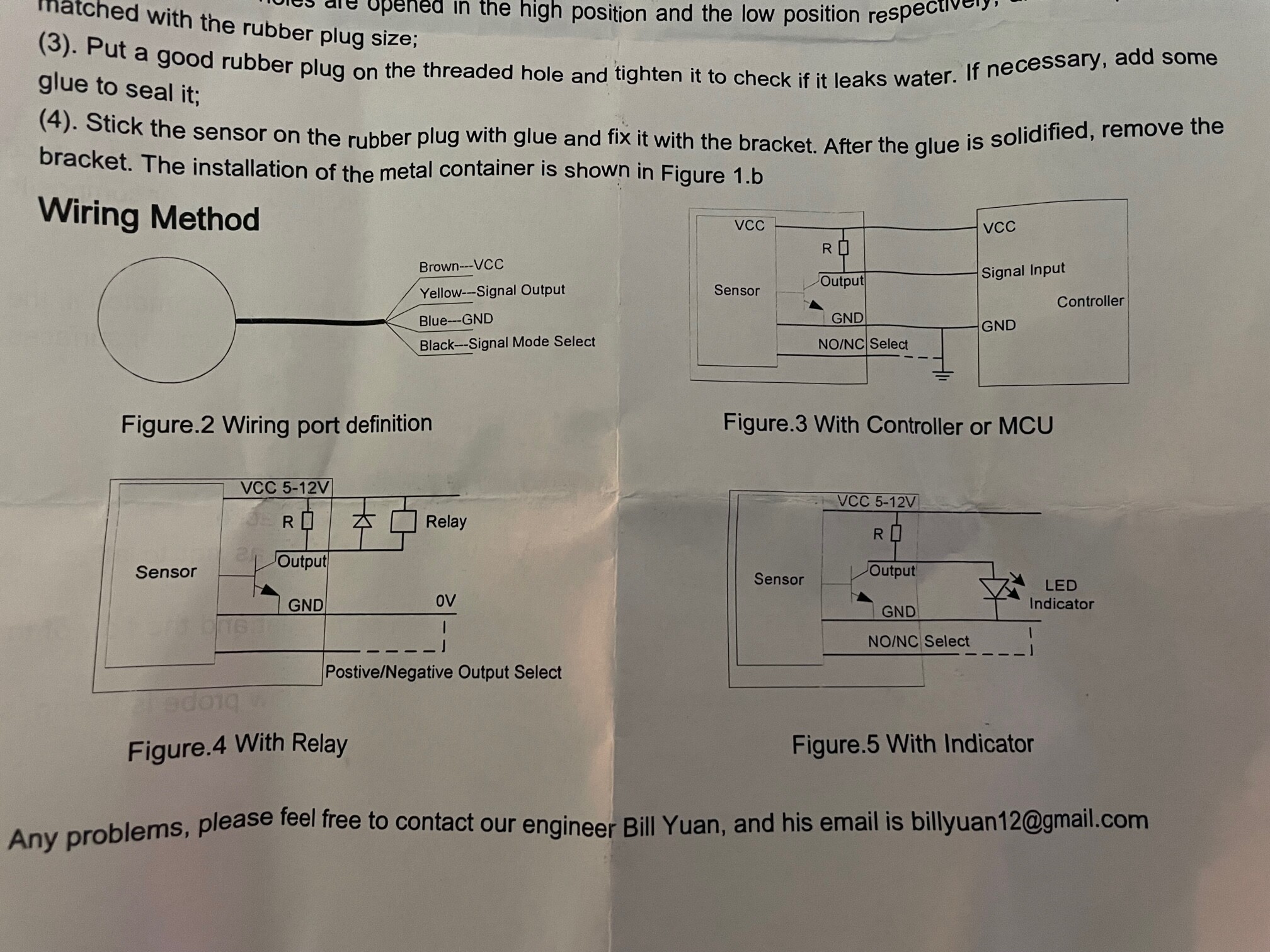
The picture show several useable versions so it ought to work.
Where did You find that 3.x volt? It could have been perfectly all right.
Posting Your code might be useful.
Below is the circuit to the best of my knowledge. So the idea behind the board is to be able to use a simple 2 wire float switch or a 4 wire optical fluid level sensor. I am trying to add my noncontact fluid level sensor to this board. Do either of you know how I can do that? If I cant I may just make an arduino to read the noncontact fluid level sensor and then just close a relay. but would prefer to not have to make another interface board if possible.
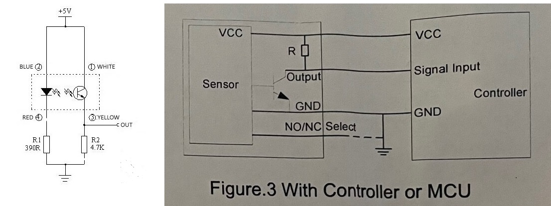
In the original circuit the transistor in the optoisolator pulled the output high.
The new sensor has a transistor that will pull the output low. The resistor designated R in the sensor will pull the output high when the transistor is not conducting.
Resistors R and R2 now form a potential divider, which will prevent the output going above a certain level.
Try removing R2, so that R can pull the output fully high.