Everything works as expected. All sensors work. Temperature is read, and the opto switches are also working as expected. However, after some up time (2-4 hours) arduino's loop just stops. Reset button brings it to live, and again 2-4 hours and loop is stopped. I did some investigation and came to the conclusion that the culprit is opto switches: with them disconnected it works more than 24 ours without stopping the loop. Also I am making a simpler board with just arduino and sensors to confirm the problem caused by them, but now I am asking why it might be so ? I suspect it is because I power sensors from 12V, but the output is connected to 5V from arduino. But judging from the diagram it open collector output. I am out of ideas. Could you please help me here ?
I can provide the code. But I am sure everything is fine there (as I said the code had been working for 12-24 hours without sensors connected).
P.S. The arduino's regulator isn't hot. It is about 47 C, and I am able to lower it to 30 C with a little fan.
Sorry there is not enough to give you an accurate answer. I have seen similar things when using micros() or millies() where the timing test was not correct and the test failed because of roll over. Mills rolls over about every 1 minutes. Check this link: https://arduino.stackexchange.com/questions/22994/resetting-millis-and-micros
I am very doubt about it. millis are unsigned long which means its maximum is 2^32 - 1. So it waaaay more than 1 minute. Everything I do in the code is
if(millis() - lastTimeCheck >= interval)
And if it's not I am not waiting -- I do other work. So I would know if it just stucked in the if.
Done. I use Arduino-CLI, so there is the run.sh script as an entry point.
[quote="ec2021, post:6, topic:1397043"]
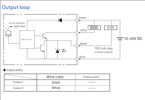
The sensors you are using seem to be kind of "Fork Light Barriers", aren't they?
[/quote]
I don't know this term, but looks so. There is infrared ray between those two "legs of greek П", if it is interrupted the transistor is open (while normally closed).
That works out to about 71 minutes.
Not knowing what the loads are, how much current each item is drawing and without the annotated schematic showing power sources etc there is not much more I can do to help.
At a first glance through your files I cannot see a software reason for your problem.
The output lines (white and black) of the Fork Light Barrier seem to switch against GND. To be on the very safe side you could measure the output voltage...
If I am not wrong the alarm pin will be set only for a very short time as status is reset to eNone immediately after that at the end of the function outside of the millis() statement. Is this ok for you?
Actually both, they have different times but the same overflow problem. This will explain it for you: Arduino millis() vs micros() - The Robotics Back-End Looking at the code you did not post I cannot give you an accurate answer.
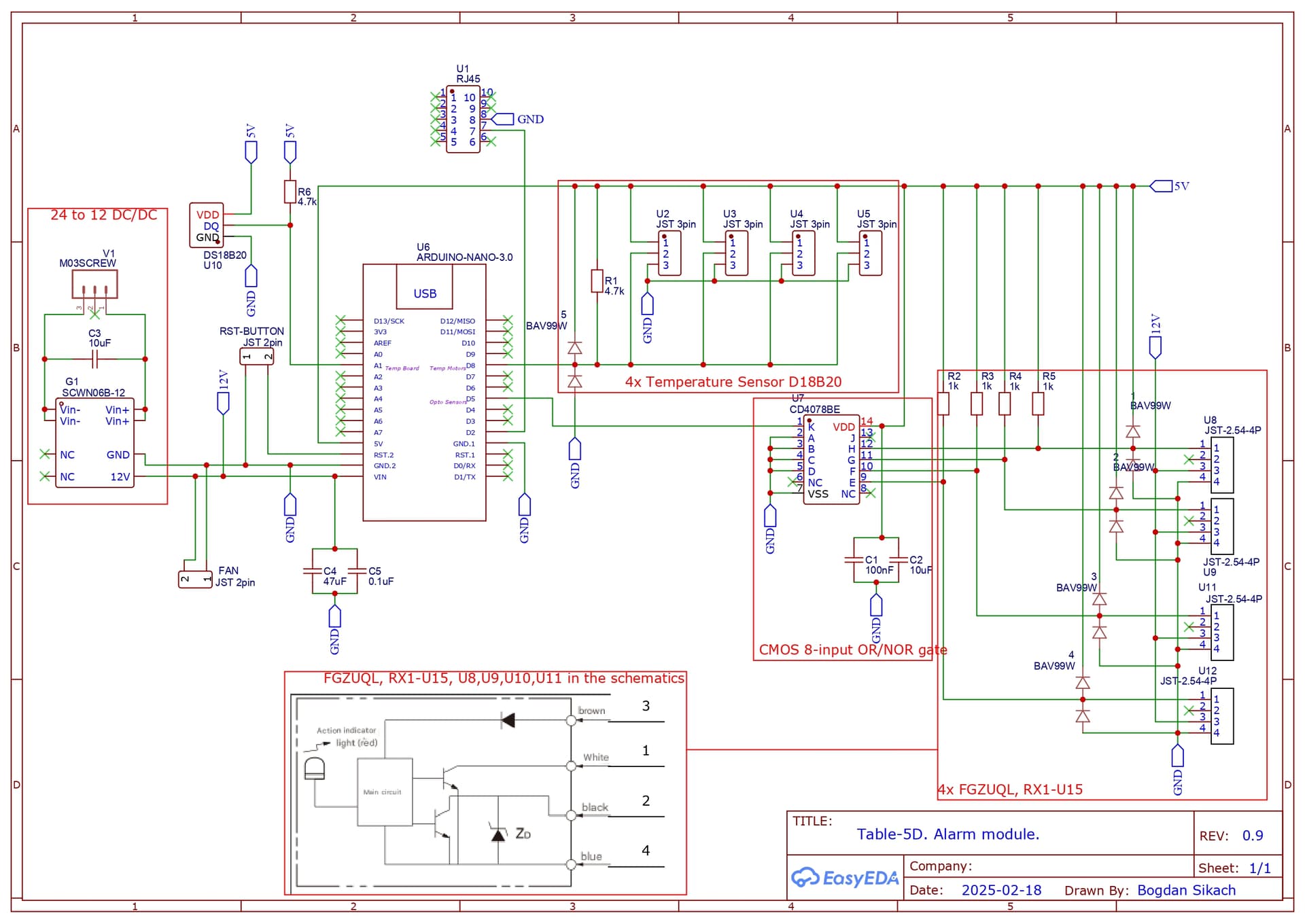
I can't make out the part number of the CD40 chip (U7). Is it a multiplexer? I see it's powered with 5V. Are you putting a 12V signal on it's input pins?
It's not necessarily true. If the reason for alarm keeps happening the alarm pin will be still high. This check function is "error handler" in some sense. So I reset the "error" after I've done with it.
That works out to about 71 minutes.
Sorry, but I don't understand why you keep saying about millis overflow. millisdon't overflow in 71 minutes either. As @ec2021 pointed out their counter overflows each ~50 days. 2^32 / 1000 / 60 / 60 / 24 = 49.71 day.
Not knowing what the loads are, how much current each item is drawing and without the annotated schematic showing power sources etc there is not much more I can do to help.
I updated the schematics. The thing is I have connectors on the board to connect the sensors. They are in the right bottom corner.
Updated also. It is CMOS 8-input OR/NOR gate. I power it from 5V from arduino indeed, but the input is also 5V as you can see: the inputs are 1k pulled up to 5V. And if sensor's open collector is closed it becomes 0V.
Note that the power supply consists of a 24V to 12V DC-DC converter, that 12v is fed into the Nano Vin. Most the peripherals are supplied by the 5V linear regulator on the Nano board.
Even 100mA of load will produce.
P = V x I = (12 - 5) x 0.1 = 0.7W.
I would say the regulator is going into thermal shutdown.
If the fault did not occur with the four sensors disconnected, its obvious.
Instead of 24V to 12V DC-DC converter, use a 24V to 5V Dc-DC converter and feed 5V DIRECTY into the Nano 5V pin and to the peripherals.
Use your DMM and monitor the 5V supply you have now and see what happens when your project fails.