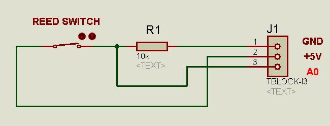
the reed switch attached to the bike is supplied from the +5V/GND of the arduino.
The value from serial monitor is okay but when I connect the monster moto's source to arduino, that is the point where there is something wrong. I get random numbers. I think, monster moto is affecting the output
reed switch acts like a button, where it can be triggered by a magnet, and it need +5V and GND.
here is the link where I got that idea. Please check this.
reed switch acts like a button, where it can be triggered by a magnet,
Yes
and it need +5V and GND.
No.
You only need to connect the reed switch between the input pin and ground on your arduino and then enable the Arduino's internal pull up resistors. This is perfectly isolated there is no need for any electrical connection to the bike.
Here is how to use inputs.
Hi,
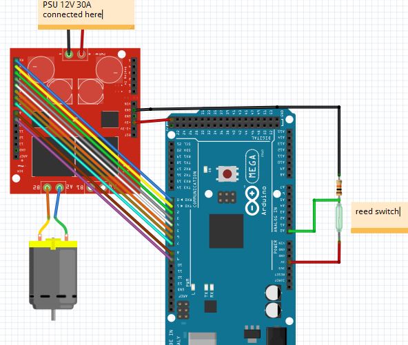
Can you please post a copy of your circuit, in CAD or a picture of a hand drawn circuit in jpg, png or pdf?
We need to see how the power supply and motor and arduino are connected, please.
Hi, the resolution is not the best, can't read the pin numbers, also Frizzing is not the best way to do a circuit. It allows you to assume connections are made.
Hand drawing it will make sure you know the connections are made.
Drawing circuit diagrams can be very therapeutic and can help you solve wiring problems quite quickly.
Especially drawing the first draft by hand, pencil and paper.
Have you got the GND of the boards connected together ,I can't see it in your diagram.
holmes4:
I suspect A0 is used by the shield. It gives the ammount of current drawn by the motor.
Yes, it is a pin conflict. A0 is one of the enable line outputs. So once you initialize the library, you're no longer reading the reed switch state, you're reading the current enable line state. Worse, when the reed switch closes, you're shorting the line to 5V, which means a huge slug of current into the pin if the output is currently low.
The connections to the Arduino are in the lower left. It uses pins A0 through A3, and D4 through D9. You want to leave D0 and D1 open for the serial port and D13 for the on-board LED. So use D2, D10, D11, D12, or A4 or higher for the reed switch. Since it's a Mega, you have digital pins higher than D13 as well, you can also use any of those.
What I've done is check the wirings and connection. Also I changed the analog pin of reed switch(A0) to A4. Based on what Shapeshifter say.
So you have not actually done anything to fix it, you just fiddled around with it and it happened to appear to function.
How about all that advice you were given?
Specifically:-
Worse, when the reed switch closes, you're shorting the line to 5V, which means a huge slug of current into the pin if the output is currently low.