Hi all
will be nice if someone with skills, Based on this library (or other project)
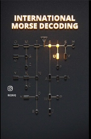
https://github.com/pdnelson/Morse-Code-Decoder-Library can made an project for morse decoder to led table like in this video
https://x.com/i/status/1879555046305841318
Nice decoding representation.
I don´t know about the liberary or other ready made code, but this seams to me like a realy nice project to try a not too complicated selfmade solution.
The basic things are quite strait forward. Measure button press timigs with millies() and create a small state machine, which is perfectly sketched in the picture above.
Some part of the idea is clear, but how should the output look like?
output to LED like DOT=1LED, LINE=2LED's (or also just one LED, but back on a wall table)
like in video
https://x.com/i/status/1879555046305841318
Will be even more nice if someone without skills uses this project as an opportunity to learn, build their skills and experience. I'm sure this forum would help and support them in that endeavour.
..true
Did you ask the person who made the video?
it was shared on X, without any info
I found a project who can be a start point, but need to have output for those LED's to represent dot dash and letter
https://www.101computing.net/morse-code-using-a-binary-tree/
L.E.
I found:
https://www.instagram.com/p/DEmApyMtMn7/
Dear yo2ldk,
What do you need, to just start?
Where is your blocking point?
What do you expect from the people here?
Do you need help, choosing the right hardware? Have you any ideas with what to start?
Do you need help with the wireing? Do you have some experience with electronics?
Do you need help with coding? Do you have some knowledge with coding?
Do you need help with the mechanical work? Do you have some construction abilities, tools and at minimum one working hand?
What you want to do, to contribute, to invest, to investigate, to come to the target?
my friend fiso42,
I am HAM Radio amateur, with experience in electronic and hardware,
I made enough projects in Arduino, I can adjust codes for my needs, but,
I'm not a programmer..just beginner in that .
Morse library or other projects on github can decode easy CW signals, but for me is hard to translate this as output for tree map with LED; if it can be made it just with two IO ports, one for dots and second for lines, or need it more, maybe multiplexed..etc.
I just see that video and is a great project to have it for our hobby, also for beginner to learn CW
I just want to made one for me, and for sure is many others, just need some help in coding
i can say if on Digital Pin 2 audio is .- (letter A) to print or be output 4 high (LED light)
but it is 26 letters and need to know how to "tell"if audio on input is .-. light ON LED 1,2 and 3 for letter R and so on to 26..
In that case how do you know it's even real, may just be a computer simulation.
Now that I look closer it does look like an animation.
for sure is not real YET, but it can be with some help ![]()
Do you have the tools to fabricate something like that?
Do you have some Arduino around to start with? Which kind?
Needed number of LEDs can be solved with the 5 x 6 LED grid.
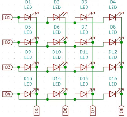
Since maximum 4 LED segments are active at once, it should be quite well working with 1/4 duty cycle with high efficiency low current LEDs. In case of a 5V Arduino with ATmega then two LEDs in a row (as long signal symbol) can be easily realized.
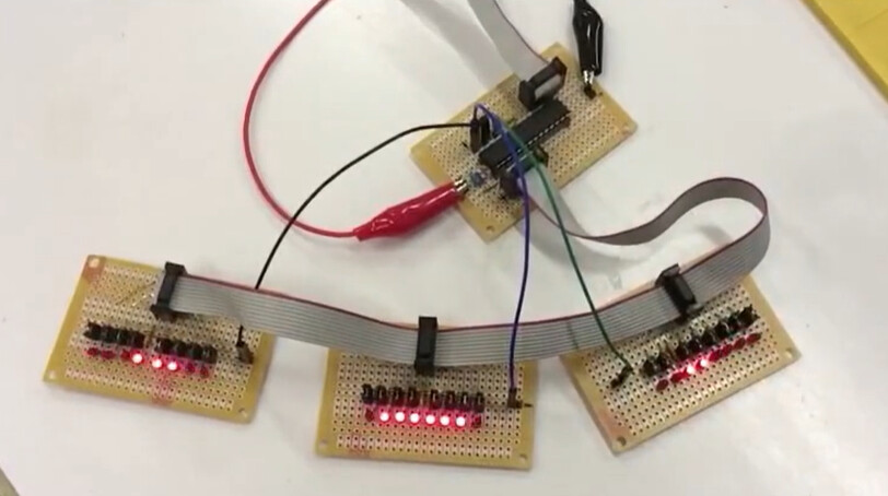
As a show case example (5x8 LED grid multiplex) connected to an ATmega8:

Thank you for reply and tips,
multiplexing is a good ideea..
I have all kinds of Arduino boards and will try somehow
now I remember long time ago I made a binary clock, need to look on his code for inspiration
Max7219 is solution ![]()
I have all I need, except software ![]()
but need to try
This looks like a nice application of light pipes.
Nowadays I think it is easier to use addressable LEDs, unless cost is a serious concern.
Or just use a Mega.
Anyway just for fun, I made a start
Here the red LEDs are dots, the green ones are dashes.
yes WS2812 is also a good solution..
Nice. It looks like you'll end up with 26 states, or a state for every terminal node if you handle more than the alphabet.
The diagram will be wired by the connections between the states. Each non-terminal state will connect via dot or dash to a child state.
I don't have enough before she texts me we are off to the beach time to take my own stab at this, but I would consider using a table to describe the wiring, and the machinery would jump from table entry to table entry as indexes into the table. Table entries for a character would be end nodes, or direct a process to one of two states based on receiving a dot or dash, a generalization of every
      if (event == DOT)
      }
        digitalWrite (LED_E, 1);
        state = STATE_E;
      }
      else // event == DASH here
      {
        digitalWrite (LED_T, 1);
        state = STATE_T;
    }
each of which would be one line in the table.
It would be easier to create, verify, maintain and extend.
I have my Amateur Extra Class FCC license, but got it after they dropped the Morse Code skills from those tests... I've had in mind to lern it, just because it's there like Everest. I found similar trees in the learning materials I googled once when I was closer to serious about it.
By practice, the tree is ingested into one's brain. Scary stuff.
a7
We wrote a neopixel dash/dot display bar and added it to the moving target which is @bobcousins simulation.
It could be part of any other approach; it is easy enough to add to anything as it has only three functions, setupDashDot(), resetDashDot() and dashDot().
We put the action call dashDot() at the top of the state_machine() function.
Try it in context here:
// totally separable DashDot display mechanism

# define N_REAL 30
# define PIN_NEOPIXEL 10

# include <Adafruit_NeoPixel.h>
Adafruit_NeoPixel track(N_REAL, PIN_NEOPIXEL, NEO_GRB + NEO_KHZ800);

int nextPixel;

void setupDashDot() {
  track.begin();

  track.setPixelColor(1, 0xff0000);
  track.setPixelColor(2, 0x00ff00);
  track.setPixelColor(3, 0x0000ff);
  track.setPixelColor(4, 0xffffff);
  track.show();

  delay(777);
}

void resetDashDot() {
  nextPixel = 0;
  track.fill(0x404040);
  track.show();
}

void dashDot(int event) {
  if (nextPixel >= N_REAL) return;

  if (event == DASH) {
    for (byte ii = 0; ii < 3; ii++)
      track.setPixelColor(nextPixel + ii, 0xff00ff);

    nextPixel += 3;
  }

  if (event == DOT) {
    track.setPixelColor(nextPixel, 0xff00ff);
    nextPixel++;
  }

  track.setPixelColor(nextPixel, 0x404040);
  nextPixel++;  // intercharacter space.
  track.show();
}
We had different colours for dashes and dots. For the strip one colour works better.
a7