I don't know for sure if this is the correct category, I apologize if it is not.
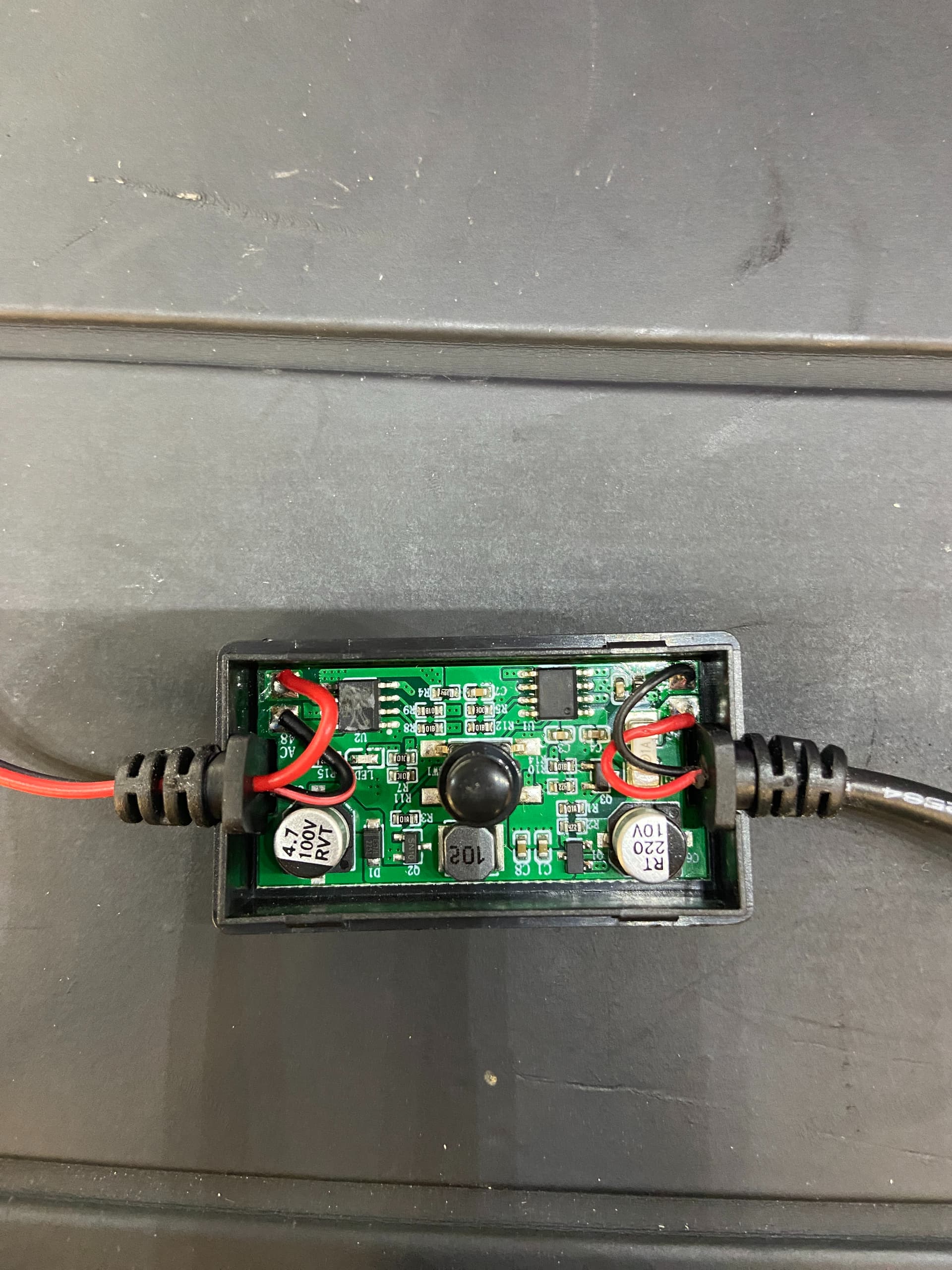
I have a bug I can’t figure out in my current project. It is supposed to receive an input, turn on a sheet of PDLC film (AKA Smart Film), wait a time, turn it back off, and then start monitoring for a new input. It should be so simple which makes this all the more frustrating haha. I’m currently using a nano. The PDLC film has a little power supply thing (that I expect is the cause of all of my problems) that goes from a usb input, through a little black box with a button, to the film. The button turns on/off the film with a press and with a hold if fades on/off. The main issue is I don’t really know what it does. Here is a picture with the case opened up.
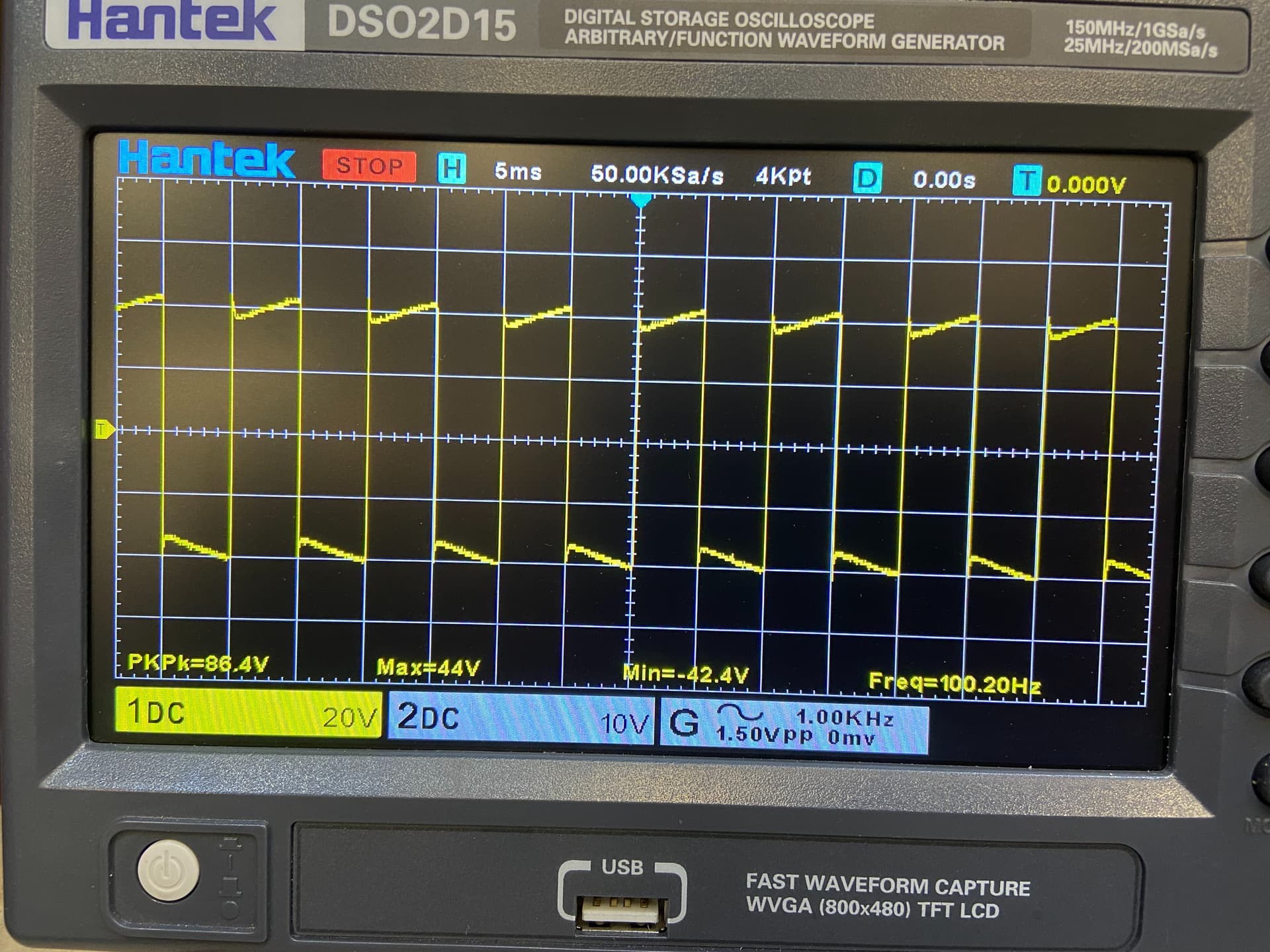
I attached an oscilloscope to the output of the power supply (I’m pretty new to using a scope, I’ve only used one a handful of times) and this is the waveform. When the button is held the amplitude grows and shrinks. The smart film company told me that their normal power supplies are 60V AC. The power supplies I have are their small sample supplies.
I found out that if I plugged in the usb the sheet would turn on and if I unplugged it it would turn off. My thought was I could just use a relay to control the 5VDC power input so I don’t have to get into how the power supply works. I then decided to try using a MOSFET for the first time. Everything seemed to work fine on my breadboard so I went ahead and soldered up a more permanent solution. I started noticing bugs on that circuit board, but when I went back to the bread board I found them there as well.
Essentially the circuit will seem to be working fine for a while and then sometimes it just freezes up. It seems to be hanging my code for some reason, or maybe it is throwing the Arduino into a reboot loop. It only happens sometimes, enough that I didn’t notice before I made my soldered board, but it always does eventually. Ive had it hang searching for an input so it never reads the button press and I’ve had it hang after the relay turns on so it never turns back off.
I’ve tried a bunch of things to try to fix it. I tried the code with and without delays. I’m back to my breadboard to make sure it wasn’t my soldered version. I originally was running 5V to Vin to power the board, so I thought maybe it wasn’t getting enough power. I ran the 5V power directly to the 5V pin and the problem persists. I added a resistor between the output pin and the MOSFET because I read that somewhere but that didn’t change it either. When I unplug the PDLC power supply from the circuit I haven’t noticed the bug yet, so I’m almost positive it is causing my issues.
I don’t know if maybe I need to add some sort of diode or something to protect the Arduino from back voltages or something. I thought I could try using the scope to find a voltage spike but I’m not sure where to look for it. Basically I’ve tried everything I can think of and I’m at the end of my know-how. I would greatly appreciate any assistance!
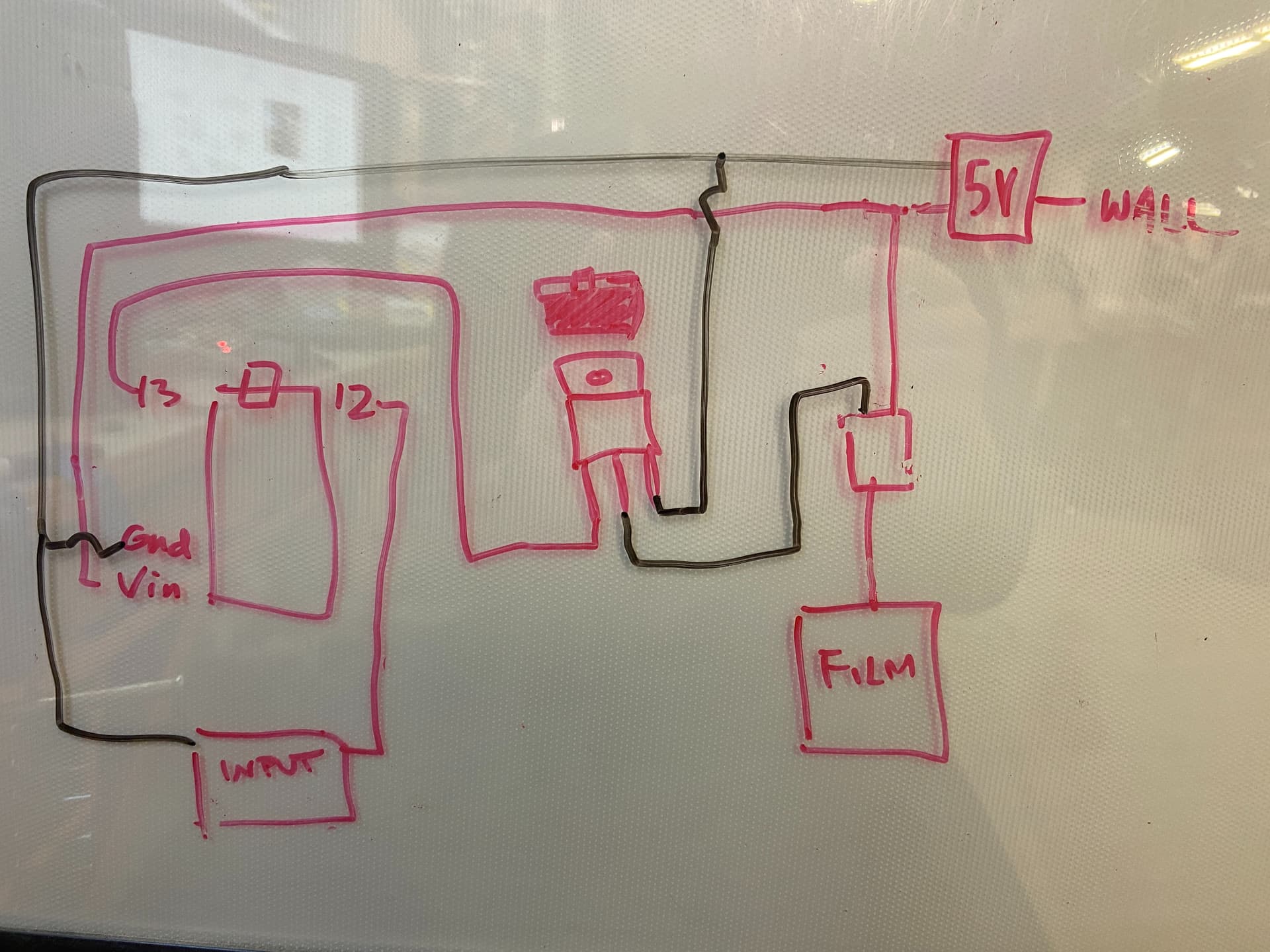
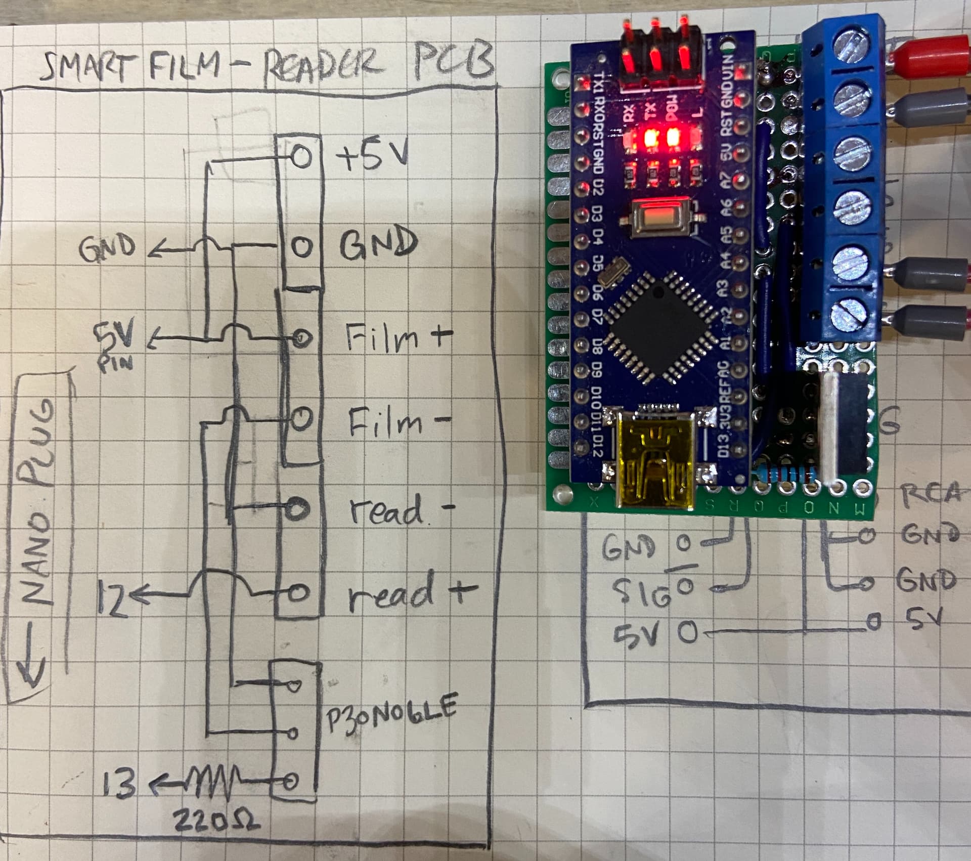
here are photos of my circuit "diagrams" and the board I soldered.
code with delay() :
const int readerPin = 12;
const int relayPin = 13;

const unsigned long readerTimeout = 10000;

void setup() {
  // put your setup code here, to run once:
  Serial.begin(9600);
  pinMode(readerPin, INPUT_PULLUP);
  pinMode(relayPin, OUTPUT);
  digitalWrite(relayPin,LOW);
}

void loop() {
  // put your main code here, to run repeatedly:
  Serial.println("nothing");
  if (digitalRead(readerPin) == LOW) {
    Serial.println("reader");
    digitalWrite(relayPin, HIGH);
    Serial.println("relay on");
    delay(readerTimeout);
    Serial.println("wait over");
    digitalWrite(relayPin, LOW);
    Serial.println("turned off");
  }
}
Thanks in advance