How to use p-channel and n-channel mosfets higher voltages.
This is very commonly questioned here, so I made an example ( simulation available in iCircuit, but schematics can be seen on webpage just fine even if you wouldn't have iCircuit)
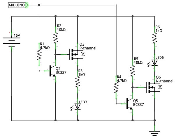
Circuit has both, n-channel and p-channel mosfet. When +5V is applied, circuit with P-channel mosfet activates, and of course, N-channel one de-activates. And vice versa.
Thoughts?
One could use N-channel mosfet with a NPN but I discovered some efficiency lost then, and also, if you wire it without NPN, to enable power in circuit with N-channel, instead of disconnecting power, you need to connect it and probably you also will need a logic level Mosfet, although, in most cases with Arduino, I guess it's better to use logic level mosfet even if you would use a NPN.
Any thoughts or mistakes?
This circuit activates +24v power source and lights a led when circuit is enabled.
Apart from the fact its a bad circuit that puts 24V onto the gate of a MOSFET? 12V or 15V is quite enough
for the vast majority, typical gate-source breakdown voltages are +/-20V to +/- 30V.
Those are not the standard symbols for power MOSFETs and the n-channel one is confusingly upside-down...
The 150 ohm base resistors are rather low compared to the 10k collector pull-ups, the circuit is going to
switch very asymmetrically (speed-wise).
I like the OP's idea. Unfortunately, as others have noted, his attempt leaves a little bit to be desired. I thought I'd contribute my version. However, I'm still somewhat new to electronics in general, so would appreciate any and all corrections:
Notes:
The p-channel requires a high from the Arduino to turn on;
The n-channel requires a low from the Arduino to turn on.
Cheers!
Dirk