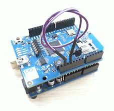
Two pins on the wifi shield will protrude over the Uno on the usb side. Insure the ICSP pins are aligned and connected correctly, and the overlapping pins do not contact any components on the Uno. Bend the pins outward a little if necessary.
Then I used a jumper from the 5v socket to the IOREF socket on the shield. The pic I attached shows the overlapping pins and the jumper, but it is jumpering the 3.3v socket to the IOREF.
Thanks for the reply. Do you have any documentation or a video perhaps to illustrate what you are talking about regarding the cables?
I'm not entirely sure what you mean by
SurferTim:
Then I used a jumper from the 5v socket to the IOREF socket on the shield. The pic I attached shows the overlapping pins and the jumper, but it is jumpering the 3.3v socket to the IOREF.
I'm quite new to all of the hardware stuff as I'm a software engineer by trade.
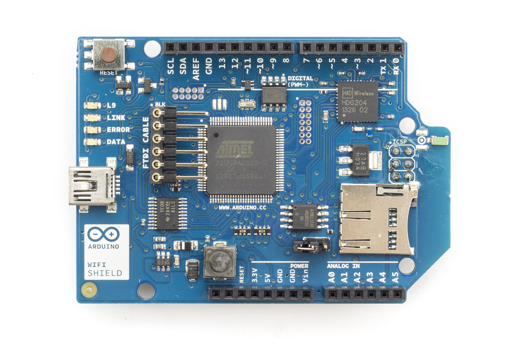
Did you not see the pic I attached? The IOREF pin needs the logic level voltage of the Arduino applied or the Arduino will not recognize the shield. I know because I have a wifi shield connected to a R2 Arduino. The Arduino would not see the shield without that jumper.
The Uno has 5 volt logic, so I connected the 5v socket to the IOREF socket with a jumper.
I used a 100 ohm resistor initially. That worked, so when I ordered some stuff from Adafruit, I included a set of male/male jumpers. These in particular are handy.
I also got male/female, and female/female jumpers. They are very handy to test new hardware.
Rather than creating a new thread for a supplementary I'll use this thread.
When I mount the shield on the aforementioned kit a red LED comes on on the main board. Could this be a power issue?
Also I need to mount an xbee expansion shield on top of the wifi shield so could you tell me what to do in regards to the earlier solution of hooking the 5V to the IOREF using male to male. Is that still required if the xbee is on top or how should I deal with that?
Not normally. The red LED indicates the wifi shield is not connected to a network. It changes to green when it connects to the AP with the ssid and passphrase in the sketch.
Upon further investigation the red LED says 'pwr' beside it yet the motors still run and the robot moves fine. Do I need to use the male to male jumper like you suggested before? I can see the 5V socket on the shield but not the IOREF that you mentioned