Hi all
I am trying to connect the MQ-7 sensor (https://www.sparkfun.com/products/9403)
As you see in the first picture on the left, it is the sensor (connected to the sensor board). Pins H1, A1 go to power, GND to ground, and B1 to Analog Read, and then to a resistor and then to ground again.
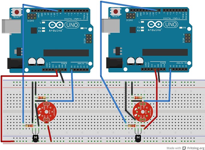
Now, I want to heat the sensor, sending 5V and 1.4V with a voltage regulator (on the right side of the first picture). How do I connect the voltage regulator with the sensor? Is my configuration on the second picture correct?
Thanks
Hi, as you have the sensor connected now without the regulator it should be running and working.
This is mode Heater Hi, for Heater Lo you connect 1.4V to H1 instead of the 5v.
Connecting H1 and G has got your heater already working.
All you should have to do is write a sketch or use the suggested sample and you should with some source of CO see it work.
Tom.... 
Thanks for the suggestion.
I know that I have to send 5V and 1.4V to heat the sensor appropriately, but I am not sure how and where to connect the voltage regulator. In my first example I use the digital pin from Arduino to send different voltage values, but I don't know where to connect the sensor. Should I connect the digital pin 9 to H1 and A1 with no other power source? Will this work?
Ok, I have narrowed it down to the following two options - see attached image. Can someone tell me if one of these two is correct? I am not very confident about the configuration, and I would appreciate some support from someone familiar with this.
Hi, what is device N?
Can you show us a circuit diagram, fritzing is not what you would call a circuit diagram. (personally I hate them.)
Even a hand drawn photographed pic would suffice.
Sorry for the gripes but we need as much info as possible from you.
I understand from the MQ data that one of the measuring methods is to power the heater pulseing from 1.4 to 5 V, is this what you are trying to do?
Neither of your layouts will do this on the MQ.
What are you expecting to program out of pin9?
Tom...
As you will see in my first attached photo (first post), there is one the left part the circuit configuration for the sensor. If you supply 5V there it will work just fine, and it will give out analog readings on the Arduino (doing a simple Analog Read from the IDE).
On the right part it is a simple voltage regulation configuration that uses a BC547B transistor (it is based on this circuit)
http://letsmakerobots.com/files/userpics/u4383/simple_dc_motor_sch.jpg
So, when I use the following code to do the voltage regulation (cycling from 5 to 1.4V), it gives me the proper readings in the LED pins.
Thus, I am trying to attach this part, with the previous so that the sensor is regulated properly.
int heatPin = 9;      // LED connected to digital pin 9
void setup(){
  pinMode(heatPin, OUTPUT);   // sets the pin as output
}
void loop(){
  analogWrite(heatPin, 75);  // analogRead values go from 0 to 1023, analogWrite values from 0 to 255
  delay(90000);
  analogWrite(heatPin, 255);
  delay(60000);
}


