Multi-port Serial on ESP32-S2

Hi.
I'm trying to eventually write a piece of code that does a "man in the middle" hack between an RFID reader and a mainboard in a piece of equipment. I need to alter the serial data sent over this link on-the-fly.

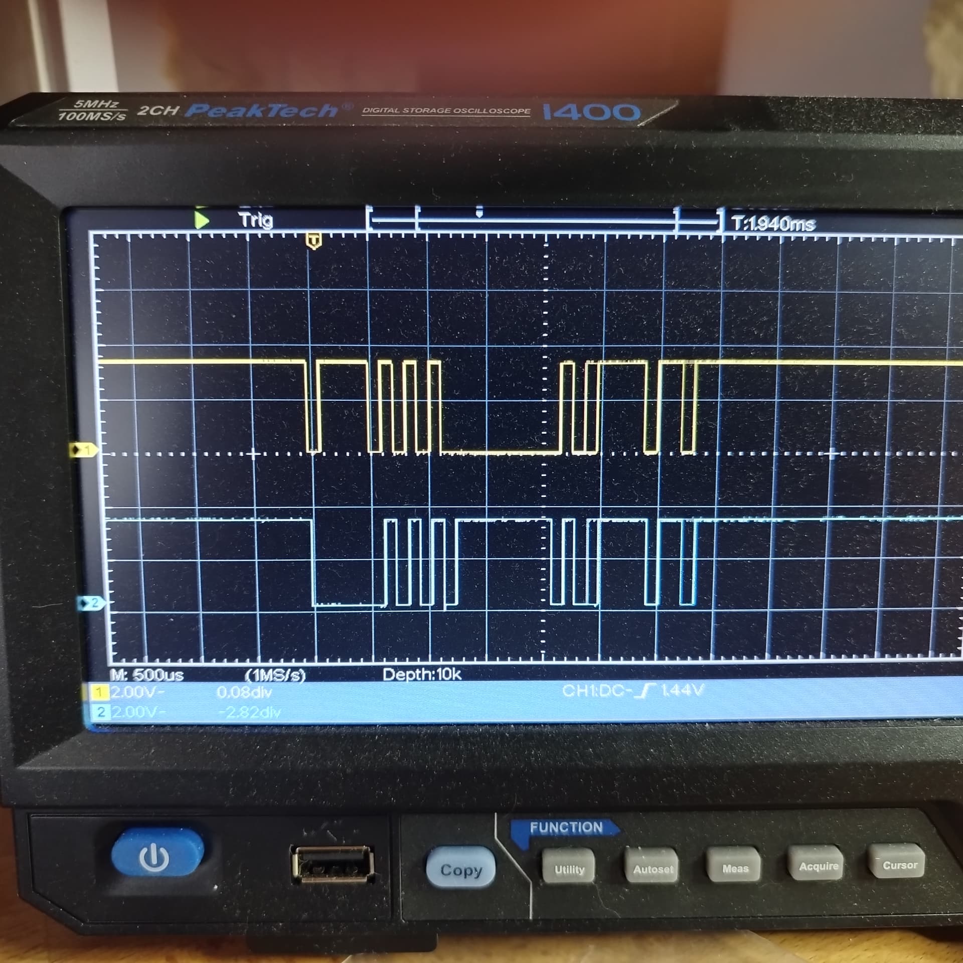
For a start I've made a simple code that just lets the two serial ports talk to each other to test the hardware part of the project, and this is giving me a hard time.

I've picked the ESP32-S2 because it has support for several Hardware serial ports, but I'm having a real hard time getting it to work. Is there something really simple I have overlooked maybe?

Data comes fine from Serial1 to Serial, but not the other way around.

I've tested the pins by swapping the definitions, so it's not because those pins are being used by something else (some of the ESP32's pins can be a bit finicky)

Any ideas?


// Tested pins: Both 18&35 receives.
#define RXD0 18  // OK!
#define RXD1 35  // OK!
// Tested pins: Both 16&33 transmits.
#define TXD0 16  // OK!
#define TXD1 33  // OK!

void setup() {
  Serial.begin(115200, SERIAL_8N1, RXD0, TXD0);
  Serial1.begin(115200, SERIAL_8N1, RXD1, TXD1);
}

void loop() {
  // This section does NOT work.
  // read from port 0, send to port 1:
  if (Serial.available()) {
    int inByte0 = Serial.read();
    Serial1.write(inByte0);
  }
  // The following section works Serial1 > Serial.
  // read from port 1, send to port 0:
  if (Serial1.available()) {
    int inByte1 = Serial1.read();
    Serial.write(inByte1);
  }
}

Oh, and I almost forgot, i'm compiling this on Arduno IDE 2.3.0 on Windows 10. The target board is ESP32S2 Dev module, and the actual hardware is the S2 Mini from Wemos.cc

Thank you in advance :slight_smile:

Well this piece of code makes both ports send as much as they can
As soon as a byte arrives on one side you send it back and it is picked up again immidiately and sended back and again and again and again.

I guess this is not the situation that is similar to your real application.

ususally a "man in the middle" listens inbetween to send the data into a third direction.
What I do not understand is why you have to

what does this exactly mean?
listening to the data and then analyse what was "heard" then doing some modification on this data and then send the modifcated data to the final receiver?
or
Do you mean listening into both directions storing the transmitted data somewhere?
For the latter you could simply use Serial to TTL-adpaters which are connected in parallel to the RFID-reader and the mainbaord

best regards Stefan

Hi Stefan. Thanks for your answer.

Maybe I wasn't too clear of what I wanted to accomplish here.

The RFID reader reads a a tag and sends out the string to the host

0xAA 0x08 0x65 0x0A 0xF6 0xC1 0x50 0x01 0x04 0xE0 0xFF

0xAA is start of frame, 0xFF is end of frame.

I need to alter the read data so the mainboard receives maybe

0xAA 0x08 0x65 0x0A 0xF6 0xC1 0x50 **0x02** 0x04 0xE0 0xFF

instead. (Bold doesn't work in code blocks, so look for the **0x02**)

That I can accomplish.
Sadly the team engineering this device made a funny control scheme where the read data is echoed back to the reader (a crude error check I guess) where the same string is echoed to the RFID reader that confirms that yes, the data is correct.

So I need to alter data /from/ the RFID reader over UART, and /back/ to the reader (with the change back from 0x02 to 0x01, otherwise the reader will say: Nope, not correct data.

Data flows from Serial1 to Serial just fine, but I get no data from Serial to Serial1, and I think this might be a limitation of the library in Arduino, and this is why I asked in this forum.

For example, this piece of test code works and "Serial0 and Serial1 is printed on both ports:

// Tested pins: Both 18&35 receives.
#define RXD0 18  // OK!
#define RXD1 35  // OK!
// Tested pins: Both 16&33 transmits.
#define TXD0 16  // OK!
#define TXD1 33  // OK!

void setup() {
  Serial.begin(115200, SERIAL_8N1, RXD0, TXD0);
  Serial1.begin(115200, SERIAL_8N1, RXD1, TXD1);
}

void loop() {
Serial.print("Serial0");
Serial1.print("Serial1");
}

So that tells me that the definition of RXD0 is not working for some reason. (I suspect) that It is always routed to the (now virtual) USB UART, as the S2 doesn't have a seperate USB/UART chip?. Is there any way around this, or do I need to go hunt for one of the old ESP32's in my box of goodies?

Let me know if it is more clear now :slight_smile:
Regards,
Per (Zapro)

Your posting says contraditionary things:

both ports print

both RX-pins can receive

both Tx can send

and this is contradictionary

If you want further help you should read your postings very carefully
BEFORE POSTING THEM
if everything that you wrote is consistant and makes sense.

Best way to do this is to write very detailed what you did.

I connected two ESP32-S2 (exact type of microcontroller

Then on µC1 I loaded this code which does only sending

// posting the code that runs on µC1 sending data 

For analysing the sending-code prints to the serial monitor
and this is the output

copy & paste what is in the serial monitor
explitly printing
Serial.println("serial send on TX-Pin no ....")

Then on µC2 I loaded this code which does only receving

// posting the code that runs on µC1 sending data 

and the receiving code prints this to the serial monitor

posting what gets printinged on the receiver side
explitly printing
Serial.println("serial received on RX-Pin no ....")

If this is too much work you
go find somebody else that enjoys fiddling around with assumings instead of detailed analysis
best place to do so is snapchat (not the Arduino forum)
best regards Stefan

Stefan, why do you need to be condescending? I felt that I described my problem as good as possible.

But let's really spell it out:

// Tested pins: Both 18&35 receives.
#define RXD0 18  // OK!
#define RXD1 35  // OK!

The above code blocks is my comments to tell me that both pin 18 and 35 is able to receive data correctly. Since some of the pins on the ESP can have funky behaviour (pull-up/down etc.), I felt it was a good reminder for myself that I tested these to work out. I've learned that you can never put too many comments in your code.

// Tested pins: Both 16&33 transmits.
#define TXD0 16  // OK!
#define TXD1 33  // OK!

This block have my comments to remind me that I tested both pins 16 & 33, and that they correctly send out valid data, either by the test sketch or by using the Serial.print function.

Simple as that.

My main code doesn't work. I expect it to receive serial data on pin X and send it back out on pin Y.
Also I expect it to receive data on pin A and send it out on pin B.

Only X to Y works. A to B does not work.

If I swap the pin definitions for X/Y and A/B then the A/B works, but X/Y stops working, hence the comment/reminder for me

// Tested pins: Both 18&35 receives.
// Tested pins: Both 16&33 transmits.

Test my code verbatim on an ESP32-S2. Tell me if it works. It doesn't work for me. I'm asking for help to get the code working. Here's a version with absolutely no comments to confuse anyone. You will find that one serial "bridge" works, whereas the other won't pass any data across.:

#define RXD0 18
#define RXD1 35
#define TXD0 16
#define TXD1 33

void setup() {
  Serial.begin(115200, SERIAL_8N1, RXD0, TXD0);
  Serial1.begin(115200, SERIAL_8N1, RXD1, TXD1);
}

void loop() {
  if (Serial.available()) {
    int inByte0 = Serial.read();
    Serial1.write(inByte0);
  }
  if (Serial1.available()) {
    int inByte1 = Serial1.read();
    Serial.write(inByte1);
  }
}

Data comes from an external source, this could be another ESP, Arduino, a USB/TTL-cable or whatever. It doesn't affect the function.

// Per.

Has the problem been soved or are we still at StefanL38 not understanding the issue?

I repeat:

void setup()
{
  Serial1.begin(9600,SERIAL_8N1,13,12);
  Serial2.begin(4800,SERIAL_8N1,10,11);
}
 
 
void loop()
{
  Serial1.println("hello 1");
  Serial2.println("hello 2");
  delay(100);  

gives compile error "'Serial2' was not declared in this scope"

This

#include <hardwareserial.h>
HardwareSerial Seriala(1);
HardwareSerial Serialb(2);

void setup() 
{
  Seriala.begin(9600,SERIAL_8N1,13,12);
  Serialb.begin(4800,SERIAL_8N1,10,11);
}


void loop() 
{
  Seriala.println("hello 1");
  Serialb.println("hello 2");
  delay(100);   
}

Results in outpunt on pin 12 but no output pin 11.
Output tested on 2-chan oscilloscope.

I gave up with the condescending "help" I've received here.

1 Like

Understandable. But ppl do get helped here, you just gotta not take anything personally.

Did you ever get it to work? I assume the code you posted compiled.

@pepe123pepe was perhaps not using a board that has a Serial1.

If you struggle yet with this, draw a block diagram of how you actually test this, complete with the external source of characters and how you are seeing those transmitted by the Arduino.

a7

I have the solution. Avoid the arduino serial begin and use the espressif function. Works.

#include "driver/uart.h"

// ESP32S2 usb cdc on boot on, usb dfu on boot off, upload mode internal usb.

const int VEBUS_RXD1=13, VEBUS_TXD1=12;  
const int VEBUS_RXD2=10, VEBUS_TXD2=11;  

const int UART_USED1 = 0; //UART_NUM_1; // serial1
const int UART_USED2 = 1; // serial2

const int LED = 15;

esp_err_t err11,err12,err13,err21,err22,err23;

void setup() 
{
  pinMode(LED, OUTPUT);
  digitalWrite(LED, LOW);
  Serial.begin(115200);
  delay(5000);
  Serial.println("Start");

  uart_config_t uart_config1 = 
  {
        .baud_rate = 9600,
        .data_bits = UART_DATA_8_BITS,
        .parity = UART_PARITY_EVEN,
        .stop_bits = UART_STOP_BITS_1,
        .flow_ctrl = UART_HW_FLOWCTRL_DISABLE, 
        .rx_flow_ctrl_thresh = 32,
  };
  err11 = uart_driver_install(UART_USED1, 256, 256, 0, NULL, 0);
  err12 = uart_param_config(UART_USED1, &uart_config1);   
  err13 = uart_set_pin(UART_USED1, VEBUS_TXD1, VEBUS_RXD1, -1, -1);

  Serial.println(err11);
  Serial.println(err12);
  Serial.println(err13);
  
  uart_config_t uart_config2 = 
  {
        .baud_rate = 9600,
        .data_bits = UART_DATA_8_BITS,
        .parity = UART_PARITY_EVEN,
        .stop_bits = UART_STOP_BITS_1,
        .flow_ctrl = UART_HW_FLOWCTRL_DISABLE, 
        .rx_flow_ctrl_thresh = 32,
  };
  err21 = uart_driver_install(UART_USED2, 256, 256, 0, NULL, 0);
  err22 = uart_param_config(UART_USED2, &uart_config2);   
  err23 = uart_set_pin(UART_USED2, VEBUS_TXD2, VEBUS_RXD2, -1, -1);
  
  Serial.println(err21);
  Serial.println(err22);
  Serial.println(err23);

  Serial.println("Done");
}

char buf1[3] = { 0xaF, 0x00, 0x55 };
char buf2[3] = { 0xa0, 0xFF, 0x55 };

void loop() 
{
  uart_write_bytes(UART_USED1, buf1, 3);
  buf1[2]++;
  uart_write_bytes(UART_USED2, buf2, 3);
  buf2[2]++;
  delay(100);   
  digitalWrite(LED, !digitalRead(LED));  
}

Gisve ouput on 2 hardware serial and the usb console.

pic measured pin 11 and 12 .
This is the code above.
Debug on usb console also works.

The esp32S2 arduino code, probably #num_uart is wrong.

I wonder if this error will be corrected or if arduino usesrs will be limited to one serial on the ESP32S2 for eternity?

So maybe that‘s something Arduino specific, but when you use PlattformIO the update to the latest Espressif Arduino plattform version has done the trick, before i also didn‘t get it to work. Now the example above is working without issues (also Serial0 and Serial1 are working as well). Maybe you can try to update the board framework/firmware/version somehow.

A post was split to a new topic: TFT display on Uno R4 Wifi

This topic was automatically closed 180 days after the last reply. New replies are no longer allowed.