I need to read from several Atlas Scientific sensors (orp, do, ec and ph) over uart one by one. The sensors are physically close to each other.
I have the following limitations:
have only 1 hardware serial port (software serial is not an option).
the length between the sensors cluster and the controller is around 10 meters.
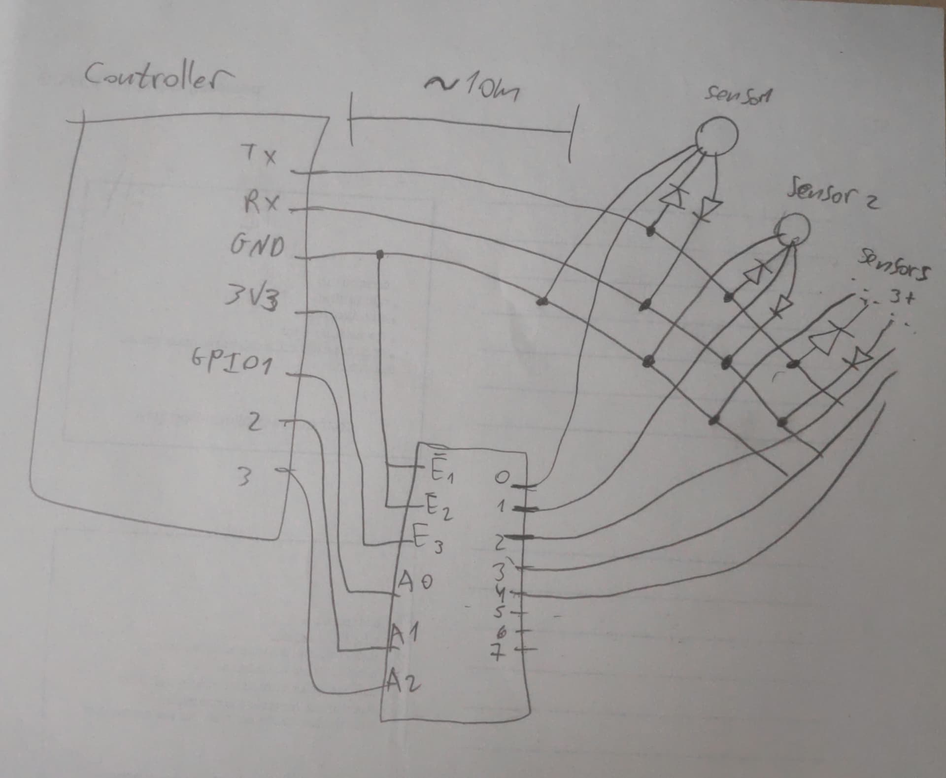
My idea for now is as in the attached image:
connecting all the sensors to the same Tx/Rx/GND wires (with diodes) and control their power with a decoder (such as 74HC238) using 3 GPIO pins, so I can enable the power for one at a time and read from it.
I prefer to use 9600 baud rate (as it's the default for these sensors).
I would like to keep my system as low-cost as possible. If I understand correctly I need 1 + X RS-485 modules (1 for the controller and X for the X sensors).
The problem with what you propose is that even with the power removed they will probably draw power from the controller to their Rx pin through their protection diodes. Search for parasitic powering.
As already suggested, try RS485.
I had a similar problem and solved it using WiFi with ESP8266s.
We used the (discontinued) Atlas Scientific Tentacle board for the interface. We used the I2C interface because I thought it was easier. The upper right corner of the schematic shows how they used a 74HCT4052 to multiplex the serial interface. tentacle_schematic.pdf (102.5 KB)
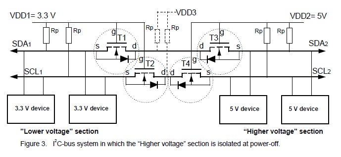
We used a level shifter that allowed the Tentacle board to be powered down between readings. They were built by hooking 2 generic level shifters back to back. In this configuration the "Lower voltage side" can also be 5V.