Multimeter Interface RS232 to Arduino :: Talking Multimeter <Help>

Hello fellow Arduino forum members,

As this is my first post (yes really), one can't really proceed without thanking everyone that participate, share knowledge experience and the occasional banter.

I have opted to join this forum, to ask for help in getting me over a hurdle, that I just take my project to the next level.
I've sectioned this post to

Project Intent
Current Research
Problem

Project Intent

In my project, I aim to :

  1. interface my Arduino Uno to a Digitek-DT4000ZC Digital Multimeter(DDM), see Digitek DT4000ZC - sigrok for details. This DMM is a rebadged TekPower TP4000ZC and all information relating to the interface apply in the same manner. Both DMMs are based on the CyrusTek ES1978Q Chip.

  2. Read the RS232 message packet (14 Bytes) and output the results to the Serial Monitor

  3. Inteface a SD Card (preloaded with Audio files)to read out (upon request) the readings.

  4. Logging the Data or results to a txt/csv/similar format to the SD card.

Current Research

I need to show my appreciation to two individuals which I admired their work on this subject:

Mastro Gippo, who's developed the same principle for a blind friend of his.
His work is given on his website: A talking multimeter | Il blog di Mastro Gippo
Which also exhibited on HackaDay Initial Posting: Say Watt? A Talking Multimeter? | Hackaday
Part-2 which used an Adafruit wave board is on : Hear Those Ohms: An Audible Multimeter for the Blind (PART 2) | Utopia Mechanicus

Also, fat16lib and his post on Multimeter SD data logger... here's a blast from the past: Arduino Forum

Problem

As the DMM connects the RS232 output using a 3.5mm Jack, I used an Audio cable with 3.5mm and I connected the TX (tip of jack) and Ground (base) to my oscilloscope. I noticed that the carrier signal and when data is sent from the DMM the voltage drops and rises (as one expects) to represent the message. However, the levels (peak to peak) are at 1-volt.

I can see that both Mastro Gippo and fat16lib have use a 10K resistor and (+5VDC) to boost the signal. Whilst, they both reported this works for them well, I was unable to replicate this.

I used the 5VDC output from my arduino uno,

DMM TX ----x-----Arduino RX
. |
. [] 10K Ohm Resistor
. |
. +5V

I've used the Serial Port Pins (0,1) and Also opted to use the SoftwareSerial port (A0,A1) @2400bps. When I compile the codes from both Mastro Gippo and fat16lib, the monitor terminal is blank (no output).

The DMM comes with an RS232 3.5mm Jack to USB cable, using that to their data logger application works fine. I am trying to read and translate the 14bytes message via my Arduino.

Any help or direction would be appreciated.

I've used the Serial Port Pins (0,1) and Also opted to use the SoftwareSerial port (A0,A1) @2400bps

You can not use the pins 0 & 1 on a Uno because that is what communicates with the serial monitor. You can use software serial though on any other pin.

Is it RS232? Because if it is then it is upside down compared with the conventional TTL signals the Arduino is expecting.

You need to see with your scope what level the signal is when there is no data being sent, this should be high, if it is low then it is indeed RS232 and it needs inverting with a transistor or the software serial needs rewriting / hacking to use upside down signals.

You need to post you code as well, read How to use this forum to ensure you post it correctly.

I have tried to read the inputs from Pin 0&1 on serial monitor and realised that I had to use another pins. So I have tried to use Software Serial and use A0 and A1. Unfortunately, I can't seem to read anything on either case.

I've connected the DMM RS232 (perhaps they just mean serial and it's not really an RS232 spec) to my scope this morning. I see that the signal is at relative high.

I've included few attachement:

  1. DigiTek-DT-4000ZC_RS232out : This is the 3.5mm tip (TX) and base (ground) connected to my scope directly.

  2. DigiTek-DT-4000ZC_RS232BoostedOut: This is the 5Vdc connected through a 10K ohm resister in series with the TX output. This is the same way that Mastro Gippo and fat16lib showed.

  3. The 14-Byte message breakdown sheet (I've reduced the file size)

  4. A simplified drawing of the setup

The links I included in my original posts show hardware construction. but to be honest, it is so simple that I can't see where I am going wrong (or anyone could go wrong)

Finally w.r.t. to including code: I didn't feel comfortable of pasting someone else's code. Especially when it's available on the forum. Therefore, I opted to include likes to the sources.

That said, without the code I might not get help, So I've included fat16lib version for now. You will notice that I've commented out the SD card calls for now.

// Log data from a TekPower TP4000ZC or Digitek DT4000ZC multimeter

// This is based on fat16lib code available on http://forum.arduino.cc/?topic=162947.0

//#include <SdFat.h>
#include <SoftwareSerial.h>

const uint8_t DMM_RX_PIN = A0;   // DMM connected to analog pin 0.
const uint8_t DMM_TX_PIN = A1;   // Analog pin 1, not used.
const uint8_t SD_CS_PIN = SS;    // SD chip select pin.

// Options for multiplier format are 1, 2, 3
#define MULTIPLIER_FORMAT 1

// If ECHO_TO_SERIAL is nonzero, print record to Serial.
#define ECHO_TO_SERIAL 1

SoftwareSerial DmmSerial(DMM_RX_PIN, DMM_TX_PIN);

// SD file system.
//SdFat sd;

// File for logging data.
//SdFile file;

uint8_t data[14]; // DMM data record
uint32_t t = 0;   // Time record was received
//------------------------------------------------------------------------------
// store error strings in flash to save RAM
//#define error(s) sd.errorHalt_P(PSTR(s))
//------------------------------------------------------------------------------
void setup() {

  Serial.begin(2400);
  while (!Serial){}  // wait for Leonardo
  Serial.println(F("Type any character to start"));
  while (Serial.read() <= 0) {}
  
  DmmSerial.begin(2400);
  
 // if (!sd.begin(SD_CS_PIN)) sd.initErrorHalt();
  
  // create a new file in root, the current working directory
//  char name[] = "DMMLOG00.CSV";

 /* for (uint8_t i = 0; i < 100; i++) {
    name[6] = i/10 + '0';
    name[7] = i%10 + '0';
    if (sd.exists(name)) continue;
    file.open(name, O_CREAT | O_WRITE);
    break;
  }*/
//  if (!file.isOpen()) error("file.open");
  Serial.print(F("Logging to: "));
//  Serial.println(name); 
  Serial.println(F("Type any character to stop"));
  while(Serial.read() >= 0) delay(10);
}
//------------------------------------------------------------------------------
char decodeDigit(uint8_t bits) {
  switch(bits & 0X7F) {
    case 0X7D: return '0';
    case 0X05: return '1';
    case 0X5B: return '2';
    case 0X1F: return '3';
    case 0X27: return '4';
    case 0X3E: return '5';
    case 0X7E: return '6';
    case 0X15: return '7';
    case 0X7F: return '8';
    case 0X3F: return '9';
    case 0X68: return 'L';
    case 0X00: return ' ';
  }
  return '?';
}
//------------------------------------------------------------------------------
char multiplierChar() {
  uint16_t s = (data[9] & 0XE) << 4;
  s |= (data[10] & 0XA);
  switch (s) {
    case 0X40: return 'n';  // nano
    case 0X80: return 'u';  // micro
    case 0X08: return 'm';  // milli
    case 0X00: return ' ';  // one
    case 0X20: return 'k';  // kilo
    case 0X02: return 'M';  // Mega
  }
  return '?';
}
//------------------------------------------------------------------------------
int multiplierExponent() {
  uint16_t s = (data[9] & 0XE) << 4;
  s |= (data[10] & 0XA);
  switch (s) {
    case 0X40: return -9;
    case 0X80: return -6;
    case 0X08: return -3;
    case 0X00: return 0;
    case 0X20: return 3;
    case 0X02: return 6;
  }
  return 99;
}
//------------------------------------------------------------------------------
char *decodeUnits() {
  uint16_t s = (data[11] & 0XC) << 4;
  s |= data[12] & 0XE;
  if (s == 0 && (data[13] & 0X4)) return "C";
  switch (s) {
    case 0X80: return "F";
    case 0X40: return "Ohms";
    case 0X08: return "A";
    case 0X04: return "V";
    case 0X02: return "Hz";
  }
  return " ";
}
//------------------------------------------------------------------------------
void printRecord(Print* pr, char sep = ',') {
  pr->print(t);
  pr->print(sep);
 
  for (uint8_t k = 0; k < 4; k++) {
    uint8_t s;
    s = (data[2*k + 1] << 4) | (data[2*k + 2] & 0XF);    
    if (s & 0X80) {
      pr->print((char)(k ? '.' : '-'));      
    }
    pr->print(decodeDigit(s)); 
  }
  // Print multiplier
#if MULTIPLIER_FORMAT == 1 
  int e = multiplierExponent();
  if (e) {
    pr->print('e');
    pr->print(e);
  }
#elif MULTIPLIER_FORMAT == 2
  pr->print(sep);
  pr->print("1e");
  pr->print(multiplierExponent());
#elif MULTIPLIER_FORMAT == 3
  pr->print(sep);
  pr->print(multiplierChar());
#else  // MULTIPLIER_FORMAT
#error Invalid MULTIPLIER_FORMAT
#endif  // MULTIPLIER_FORMAT

  pr->print(sep);
  pr->print(decodeUnits());
  if (data[0] & 0X08) pr->print(" AC");
  if (data[9] & 0X01) pr->print(" Diode");
  if (data[10] & 0X04) pr->print(" %");
  if (data[11] & 0X02) pr->print(" REL");
  if (data[11] & 0X01) pr->print(" Hold");
  pr->println();  
}
//------------------------------------------------------------------------------
// Read record.  Abort read if Serial data is available.
void readRecord() {
  uint8_t index = 0;
  do {
    int d = DmmSerial.read();
    if (d < 0) continue;
    uint8_t ib = d >> 4;
    if (ib < 1 || ib > 14 || index != (ib - 1)) {
      index = 0;

      continue;
    }
    data[index++] = d;
  } while (index != 14 && !Serial.available());
}
//------------------------------------------------------------------------------
void loop() {
  if (Serial.available()) {
//    file.close();
    Serial.println("Done");
    while (10);
  }

  uint32_t sec = millis()/1000;
  if (sec <= t) return;
  t = sec;
/*  printRecord(&file);
  file.sync();
  */
#if ECHO_TO_SERIAL
  printRecord(&Serial);
#endif ECHO_TO_SERIAL
}

TP4000ZC_serial_protocol_reducedSize.pdf (263 KB)

Are you sure that the output is on the tip and sleeve of the connector and not on the tip and ring?

Given you only have 1V output you are not going to see this on a digital pin, so I would use two transistors to get the voltage up to proper digital levels.

That said, without the code I might not get help, So I've included fat16lib version for now. You will notice that I've commented out the SD card calls for now.

Very strange code, it does nothing about reading the software serial input. Simplify it so all it does is echo what it receives on the software serial input to the hardware serial output. Forget all that "press a key to send" stuff.

Thanks a lot Mike,

I have tested the ring of the 3.5mm and couldn't see any change.

I will try to find somet ime to test (amplify) further and report back. I am trying to develop this project for a blind friend of mine (pretty much like Mastro Gippo did).

again... thanks

I have been doing some testing and got some positive results (but the project is still in progress). but here's some feedback

Grumpy_Mike:
Are you sure that the output is on the tip and sleeve of the connector and not on the tip and ring?

So the sake of good order, the answer is yes.

Grumpy_Mike:
Given you only have 1V output you are not going to see this on a digital pin, so I would use two transistors to get the voltage up to proper digital levels.

I had my doubts for the TTL level regards a LOW state between 0 and 0.8v and HIGH state between 2 and Vcc (in my case 5v). Boosting the weak 1v serial output signal with the +5V and 10K ohm, lifted the logic to the needed High state, but it would also mean that it would never drop down to the the a LOW state.

I've used a PNP transistor few resistors and I can now take my serial signal and transpose it on needed voltage between 0 and +5V.

Grumpy_Mike:
Very strange code, it does nothing about reading the software serial input. Simplify it so all it does is echo what it receives on the software serial input to the hardware serial output. Forget all that "press a key to send" stuff.

You are right, It seemed as if I was tackling two issues rather than focusing on one. I took your advice on board and used the following code.

#include <SoftwareSerial.h>
// Digital Multimeter Alternative Serial Port A0=RX, A1=TX (Not Used)
SoftwareSerial DMMSerial(A0, A1); 

void setup() {
// set the baudrate for the Serial port
  Serial.begin(2400);

// set the baudrate for the DMMSerial port
  DMMSerial.begin(2400);
}

// Loop collecting data and printing to Monitor
void loop() { 
  if (DMMSerial.available()) {
    Serial.write(DMMSerial.read());
  }
}

I compared the serial string read on the serial monitor through the Arduino A0 (DMMSerial) and a monitor of the native cable supplied with the DMM on another COM port and result are identical!

Using SoftwareSerialExample Sketch DMM reading temp at 26.3 Held
'=E[g~‰Ÿ °ÁÐä'=E[g~‰Ÿ °ÁÐä'=E[g~‰Ÿ °ÁÐä'=E[g~‰Ÿ °ÁÐä'=E[g~‰Ÿ °ÁÐä'=E[g~‰Ÿ °ÁÐä'=E[g~‰Ÿ °ÁÐä'=E[g~‰Ÿ

Connecting the Multimeter to using the usb port and using monitor just to read the com port.

'=E[g~‰Ÿ °ÁÐä'=E[g~‰Ÿ °ÁÐä'=E[g~‰Ÿ °ÁÐä'=E[g~‰Ÿ °ÁÐä'=E[g~‰Ÿ °ÁÐä'=E[g~‰Ÿ °ÁÐä'=E[g~‰Ÿ °ÁÐä'=E[g~‰Ÿ

Hurray!!! Now to the next steps.

I intend on writing up this project in more details and proper sketches to share once I am close to the finish.

Thanks again...

Good progress.

Now instead of displaying the data as ASCII characters display it as hex, with a space between each character so you can check the bit pattern against the data format you posted before.

I finally have sometime to pull everything together and managed to get it working.

Project Brief:

In a nutshell, this project is interfacing a Digital Multimeter to an Arduino. The Arduino has a MicoSD Card loaded with Audio files attached. The Arduino is also connected to a Speaker.

The Arduino reads the serial message from the DMM and outputs an Audio message to the speaker.

The project is made for a blind engineer as well as help to another sighted engineer that may not want to always check a multimeter display whilst testing.

Details:

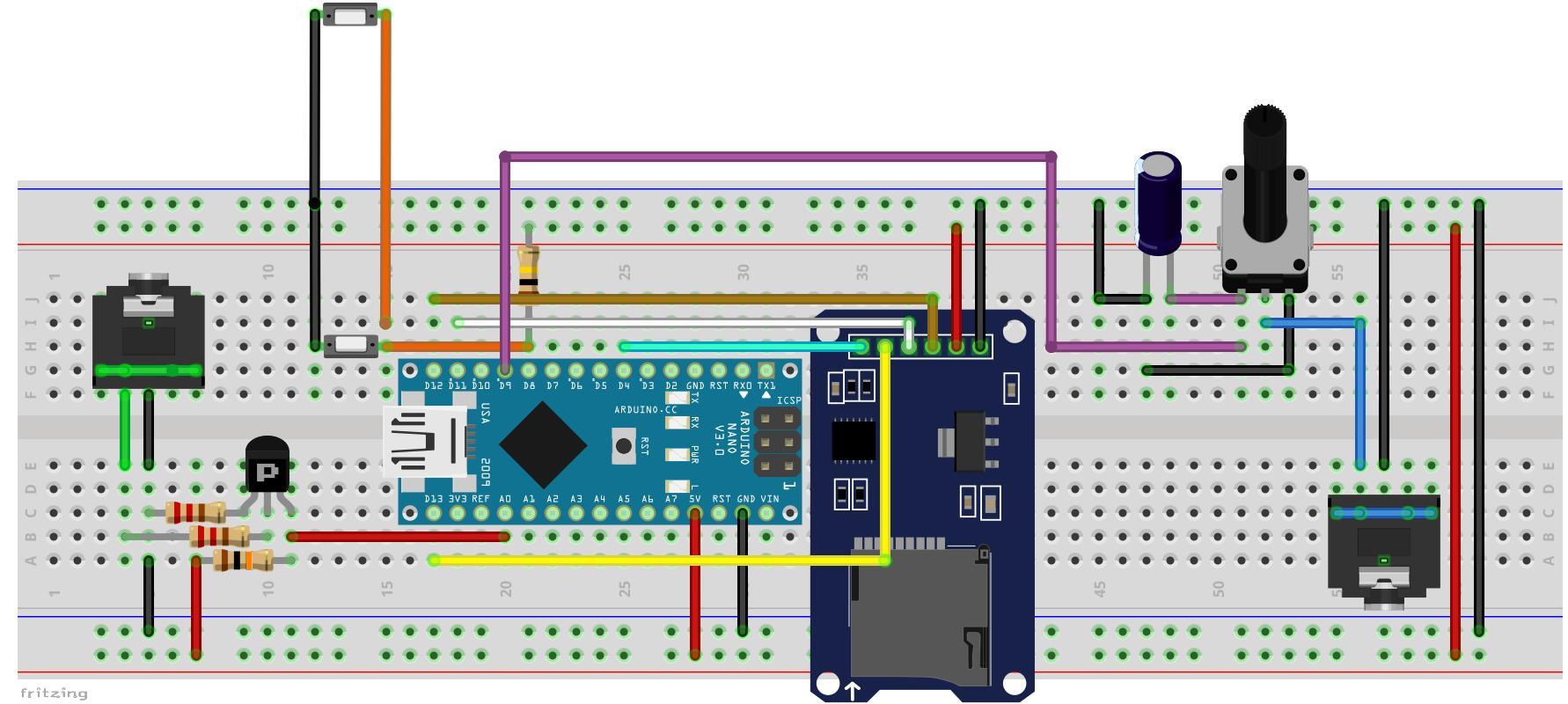
I've prototyped the project on a breadboard to test functionality. I've written a sketch to read and display the result from the DMM to the Serial Monitor, this is included in this post.

Mike's advice on connecting the DMM Serial communication to another Anagloue Pin and declare that as a different serial port was valuable. This allows the processing and monitoring of the communication on the Arduino's IDE serial monitor. basically read at A0 and push it to Serial monitor.

The serial input from the multimeter (0-1V) needed further amplification to 5V be make it legible by the Arduino. I've use a PNP transistor to shift the level up. I've included a picture of the oscilloscope output.

Now that the Arduino can read the message from the DMM, it was time to look at the code. Cristiano Griletti (Mastro Gippo) code was originally created for a similar application. I have not had to alter it a lot. However, where this is done a comment was entered.

Essentially there are 4 tabs:

1) TalkingMultimeter_V1.0
The main sketch for definitions and calls to other functions.

2) inc_14ByteMsg.h
This library goes through the 14 byte message received from the DMM

3) DMM_Reading
Tranlating the DMM message into reading

4) Group_Numbers
puts the numbers together, to be then called as audio. For example so a reading of 234.5 mA would call various individual audio files, so 234.5mA = two, hundred, Thirty, four, point, five, milli, and amps.

I've also had to record new audio files of the numbers, units and DMM status. The code was altered to call the respective files. As I have used the SimpleSDAudio.h library, I've had to convert the .wav files to .asf files. these are described in details on SimpleSDAudio – Hackerspace Ffm, as such I will no not go into details here.

I've included the audio files to this post. Note, during the build of the project, I've placed all the audio files on the root of the microSD card for the Arduino to call them upon request.

At this stage, the project was coming along very well. I've connected the output to a cheap chinese speaker (I liked the Gippo's idea), the speaker had a builtin 3.5mm cable so I've built a female audio socket on my board to connect the output from the Arduino. This simplifies the build and make it simpler to store away. That said, the Arduino Audio output (Pin 9), needed a smoothing capacitor. I found a 3.3uF works best to filter out the high frequencies. the suggested 100nF by SimpleSDAudio.h didn't do it for me!

Upon testing the project and found it successful, I've transferred everything into a project box and mounted the Variable 50K resistor (to control the volume) and placed a button on the box to request read out. This button is in addition to the button mounted on the DMM probe. I though if you are testing, you wouldn't want to let go of the probes to press the button on the box and request a reading. At the same time, there are measurements that would need the probes connected; The DMM comes with a Thermocouple probe to measure temperature, I felt a button on the box will come handy in such applications.

Included in the attached zipped file:

  • The sketch and relevant files (see 1-4) above.
  • TalkingDMM_Numbers_Audio.zip : Numbers Audio files needed
  • TalkingDMM_Units_Audio.zip : Units Audio files needed See NOTE below

Note: I've had to split the Audio files on two zipped files to be able to upload it to the forum. Unfortunatley, I can't upload both files on one post. You will need to download the second (TalkingDMM_Units_Audio.zip) file from my next post and extract both files to the root of the microSD Card to be able to hear the full DMM reading.

In addition, I've included the:

  • DMM_DT-4000ZC_CommsMsgChk : Simple sketch to check comms from DMM
  • Breadboard Layout : TalkingDMM_Breadboard_Layout_V1.0
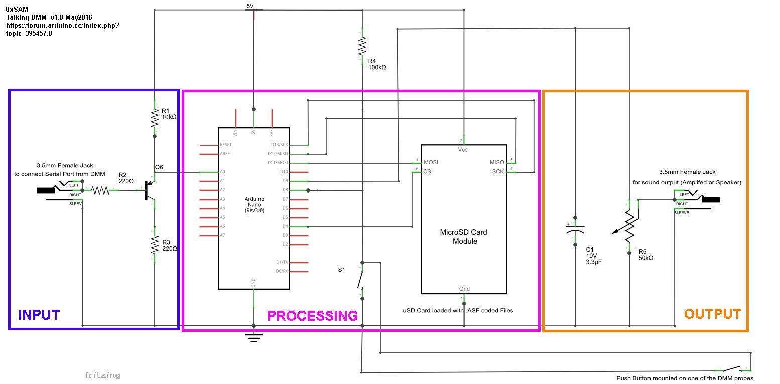
  • Circuit Schematic : TalkingDMM_Schematic_V1.0
  • Oscilloscope Trace : SerialComms_TTLMonoRS

The Material List:

  • Digitek-DT4000ZC Digital Multimeter(DDM), see http://sigrok.org/wiki/Digitek_DT4000ZC for details. This DMM is a rebadged TekPower TP4000ZC and all information relating to the interface apply in the same manner. Both DMMs are based on the CyrusTek ES1978Q Chip.
  • Arduino (I used Nano, however any type will work based on budget and space required)
  • PNP transistor, I happen to have SS8550 Datasheet: Intelligent Power and Sensing Technologies | onsemi
  • A Catalex microSD Adapter
  • A microSD (obviously!), The audio files are about 3.5MB
  • 2x Female 3.5mm Audio Jack
  • 3.5mm audio cables male on both ends.
  • Cheap Speaker with 3.5mm cable (to connect to project box).
  • 3.3uF I've used electrolytic Capacitor
  • 50K Variable Resistor (potentiometer)
  • 2 x 220 Ohm Resistor colour code: Red-Red-Brown
  • 1 x 10K Ohm Resistor colour code: Brown-Black-Orange
  • 1 x 100K Ohm Resistor colour code: Brown-Black-Yellow
  • Means to power up your Arduino power supply or power bank

The project proved easy and very useful. Therefore I've decided to share it with everyone.

DMM_DT-4000ZC_CommsMsgChk.zip (854 Bytes)

TalkingDMM_Numbers_Audio.zip (1.01 MB)

TalkingMultimeter_V1.0.zip (9.64 KB)

All, Unfortunately I exceeded the attachment upload limit on the original post.

So, I've had to include the Units' audio files in the separate zipped file and upload here. sorry!

So here are the audio file containing the units attached here.

Good luck to you ... and if you have any ideas, then please share here.

TalkingDMM_Units_Audio.zip (916 KB)

Would you consider building one for me? I am blind and need this for my business. I would pay a reasonable amount for your time and materials.