Hi, I want to control multiple (like 5?) fans with an arduino/microcontroller.
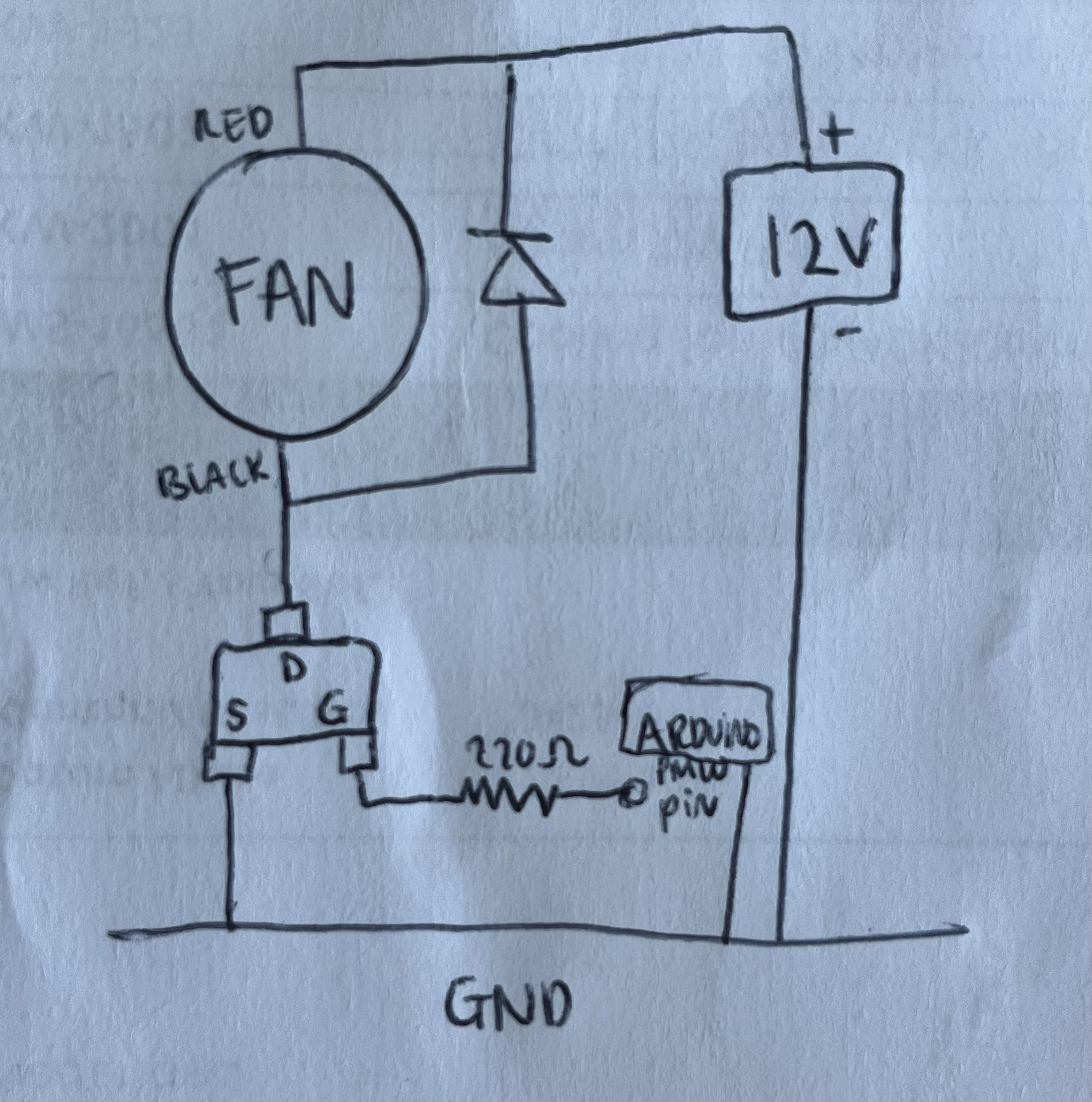
I started with wanting to control multiple 12V fans, and so I figured the way to go was like this, where I connect the black wire of each fan to the drain of the mosfet, the source to GND, the gate to a 220ohm resistor and then to a PWM pin of the arduino. I got a 12V 2A power supply for all this.
Now I found this 5V fan, which feels stronger in wind than my 12V test fan, so I'd like to use it instead. Anyways, I got stuck thinking about how to power these. The Arduino doesn't provide enough current (0.4A only?) to power it, but my power supply has too much voltage.
My questions:
Will too much voltage from the 12V power supply fry the 5V fans?
If I connect the 12V supply to the barreljack of the arduino, will it provide more current to power the 5V fans from the 5V pin?
Any tips how to go best about powering the fan installation?
My first option fans were 12V, so I got a 12V power supply for this.
The new one (which I linked) is 5V.
My question is about multiple 5V fans.
I'm wondering if I can use my 12V power supply to power the 5V fans.
You shouldn't do that. When the MOSFET is off you have 12V on the fan positive wire and the Arduino PWM pin connected to the fan, with nothing on the fan negative connection. You have a path for current from 12V through the fan to the Arduino. If you have not damaged it consider yourself lucky.
You can use 12V to 5V step down converter, but honestly, doesn't make sense to me.
5V2A power supply doesn't really cost more and most of people have those laying around (usb chargers).
Thanks for the schematic, perfect example of why we ask people to post one at the start of a topic. From your initial description I thought your 12V fan had 3 wires: Positive, negative and PWM. Your schematic for the 12V fan is much clearer than your description. Your schematic for 12V is fine, you can do that.
For the 5V fan that also looks OK, although I'm not sure of the function of the yellow and blue wires.