Hi all!
I have developed a project consisting in 16 mlx90514 ir sensors connected to an ElegooKit arduino mega vía SDA and SCL through several meters of wire. I have also connected an DS3231 rtc to the same pins. I have managed to make everything work properly when connected on their own and It even works when some of the MLX and the RTC at the same time but not all at the same time. Then the rtc does not begin() (RTClib.h) or it begins but the time is fixed. I also use the wire .h lib for the MLX
I have read a lot and I realize I may have several problems, too many devices on the same i2c bus and too much cable length leading to too much capacitance.
I don’t have an address conflict. IR Sensors are 0x1A to 0x4D and rtc is 0x68
…what is the simplest solution, pull up resistors? multiplexer? I think I have already tried the 2 ways to connect SDA/SCL.
Any help will be appreciated. I will share the code if needed but I don’t think is the problem.
You link is to the data sheet of the chip, that clearly doesn't have a pull up resistors. Yes it shows them on a typical circuit, but it is my guess that you have not got just the chip but, the chip built into a breakout board with other components on it.
If that is correct there may or may not have the pull-ups on the board, or they may be connected on the board and are enabled or disabled with a solder link.
Can you post a link to where you bought the board from.
From a review of this product on the UK Amazon site:-
Reviewed in the United Kingdom on 28 August 2018
Pros:
The clock module is self contained so easy to use with I2C communications once you know the base address (0x68 or 104 decimal). Not mentioned in the description is the built in serial EEPROM giving 4 kBytes of storage, this also uses I2C communications and again you need the base address (0x57 or 87 decimal), board has three addressing links to modify the base address of the EEPROM in the range 0x50 to 0x57.
Cons:
Circuit has built in charging circuit so it is dangerous to use the non rechargeable batteries supplied with the device, diode on the board needs to be removed to isolate the charging circuit.
No information was supplied with the unit but found schematic and address details of the two devices by searching the internet. To use the device you must know the base address of each device.
It is still not clear if there is a connected pull up resistor on each board, or what the value is. Could you measure the resistance between the Vcc and SDA line please with your multimeter with nothing connected to the module, and the battery removed. Then report back the reading you get.
Now the data sheet for this module says:-
The MLX90614 supports a 7-bit slave address in EEPROM, thus allowing up to 127 devices to be read via two common wires.
What have you done to change the address in EEPROM for each of the devices you have?
Each device on an I2C bus must have a different address.
I suggest that you run the I2C scanning program with just one of these connected to see the address it is. Repeat this operation for all your 16 devices, not forgetting to remove the power from your Arduino before swapping to the next module.
See if these addresses match the addresses you are using in the software.
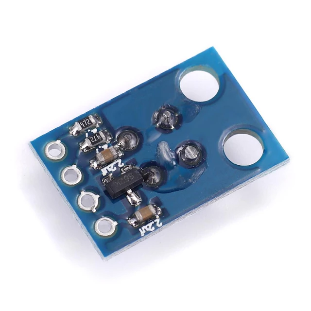
The rear of your sensor modules shows 2x 4K7 pull-up resistors. These are the small black rectangles with "472" written on them and will need to be removed from each module.
can you develop please? what are the consequences of removing them? I am afraid they will not work anymore
the IR sensors part works great, I was looking more for an answer to make the RTC work
I²c pull-up resistors should be in the range 2K to 10K. These are in that range, but 16 of them in parallel is equivalent to 1/(16*(1/4700)) = 293 ohms, which is way below 2K, and so the bus won't work. That's why you need to remove them.
It may not be the only reason the bus is not working. The long cable lengths can be a problem, as you know, and as @Grumpy_Mike points out, you need to change the addresses of 15 of your 16 sensors so that all 16 are unique.
The MLX allows a change of address and I have confirmed they are different
see the doce below for my method
/******************************************************************************
MLX90614_Set_Address.ino
Configure an MLX90614 to use a new I2C address.

This example demonstrates the setAddress function.
If an MLX90614 is configured for the default address (0x5A),
it'll change the address to a new address (0x5B).
If the Arduino can communicate with an MLX90614 on the new
address, it'll print the device's ID registers.

Note: for the new address to take effect, you need to cycle
power to the MLX90614.

Hardware Hookup (if you're not using the eval board):
MLX90614 ------------- Arduino
  VDD ------------------ 3.3V
  VSS ------------------ GND
  SDA ------------------ SDA (A4 on older boards)
  SCL ------------------ SCL (A5 on older boards)

Jim Lindblom @ SparkFun Electronics
October 23, 2015
https://github.com/sparkfun/SparkFun_MLX90614_Arduino_Library

Development environment specifics:
Arduino 1.6.5
SparkFun IR Thermometer Evaluation Board - MLX90614
******************************************************************************/

#include <Wire.h> // I2C library, required for MLX90614
#include <SparkFunMLX90614.h> //Click here to get the library: http://librarymanager/All#Qwiic_IR_Thermometer by SparkFun

IRTherm therm; // Create an IRTherm object to interact with throughout

void setup()
{
  Serial.begin(115200); // Initialize Serial to log output
  Wire.begin(); // Join I2C bus

  // check if qwiic IR thermometer will acknowledge over I2C
  if (therm.begin(0x5A) == false ) {
    Serial.println("Qwiic IR thermometer did not acknowledge! Running I2C scanner.");
  }

  else {
    Serial.println("Device acknowledged!");

    Serial.println();
    Serial.println("Enter a new I2C address for the Qwiic IR Thermometer to use!");
    Serial.println("Don't use the 0x prefix. For instance, if you wanted to ");
    Serial.println("change the address to 0x5B, you would type 5B in the serial");
    Serial.println("input bar and press enter.");
    Serial.println();
    Serial.println("One more thing! Make sure your line ending is set to 'Both NL & CR'");
    Serial.println("in the Serial Monitor.");
    Serial.println();
    Serial.println("Note, for the new I2C address to take effect you need to power cycle");
    Serial.println("the MLX90614.");

    // Wait for serial data to be available
    while (Serial.available() == 0);

    if (Serial.available()) {
      uint8_t newAddress = 0;
      String stringBuffer = Serial.readString();
      char charBuffer[10];
      stringBuffer.toCharArray(charBuffer, 10);
      uint8_t success = sscanf(charBuffer, "%x", &newAddress);

      if (success) {
        if (newAddress > 0x08 && newAddress < 0x77) {
          Serial.println("Character received and device address is valid!");
          Serial.print("Attempting to set device address to 0x");
          Serial.println(newAddress, HEX);

          if (therm.setAddress(newAddress) == true) {
            Serial.println("Device address set succeeded!");
          }
          else {
            Serial.println("Device address set failed!");
          }

          delay(100); // give the hardware time to do whatever configurations it needs

          if (therm.isConnected()) {
            Serial.println("Device acknowledged on new I2C address!");
          } else {
            Serial.println("Device did not acknowledge on new I2C address!");
          }
        }
        else {
          Serial.println("Address out of range! Try an address between 0x08 and 0x77");
        }
      }
      else {
        Serial.println("Invalid text, try again.");
      }
    }
    delay(100);
  }
//  byte address;
//  if (!therm.readID()) // Try reading the ID registers
//  {
//    // If the read fails, try re-initializing with the
//    // new address. Maybe we've already set it.
//    therm.begin(newAddress);
//
//    if (therm.readID()) // Read from the ID registers
//    { // If the read succeeded, print the ID:
//      Serial.println("Communicated with new address.");
//      Serial.println("ID: 0x" +
//                     String(therm.getIDH(), HEX) +
//                     String(therm.getIDL(), HEX));
//    }
//    else
//    {
//      Serial.println("Failed to communicate with either address.");
//    }
//  }
//  else
//  {
//    // If the read suceeds, change the address to something
//    // new.
//    if (!therm.setAddress(newAddress))
//    {
//      Serial.println("Failed to set new address.");
//    }
//    else
//    {
//      Serial.println("Set the address to 0x" + String(newAddress, HEX));
//      Serial.println("Cycle power to try it out.");
//    }
//  }
}

void loop()
{
  // If no I2C device found or Qwiic IR thermometer is set to new address,
  // scan for available I2C devices
  byte error, address;
  int nDevices;

  Serial.println("Scanning...");

  nDevices = 0;
  for (address = 1; address < 127; address++) {
    // The i2c_scanner uses the return value of the Write.endTransmission()
    // to see if a device ddi acknowledge to the address.
    Wire.beginTransmission(address);
    error = Wire.endTransmission();

    if (error == 0) {
      Serial.print("I2C device found at address 0x");
      if (address < 16)
        Serial.print("0");
      Serial.print(address, HEX);
      Serial.println(" !");

      nDevices++;
    }
    else if (error == 4) {
      Serial.print("Unknown error at address 0x");
      if (address < 16)
        Serial.print("0");
      Serial.print(address, HEX);
    }
  }
  if (nDevices == 0)
    Serial.println("No I2C devices found\n");
  else
    Serial.println("done\n");

  delay(5000);  // Wait 5 seconds for next scan
}
Please also keep in mind that the 16 sensors work perfectly even with the RTC, could I gain anything from removing the pull up resistors of the RTC?
The IR sensors are too precious (hard to get) for me right now to risk damaging one
Are you saying that all 16 sensors plus the RTC together, simultaneously, works ok? Or each sensor works with the RTC if the sensors are connected one at a time?
Adafruit sells the Melexis sensor as a 5V version and a 3V version, so then you know what to buy for a project that is 5V (with a 5V Arduino board) or for a project that is 3.3V (with a 3.3V Arduino board).
Which version is on your module ? Can you power the module with 5V and then measure the 3 pins of the voltage regulator ?
If it is the 3.3V version, then you may not connect the 5V I2C bus from the Mega to it.
The Elegoo Mega seems okay but that does not mean that it is the best board for your project.
Can you show a photo of the wires/cables of the I2C bus. Keep SDA away from SCL, they should not be next to each other in a cable.
Removing those 4k7 from all the modules is not hard when you know how Some heat up both sides quickly and wipe it from the board. I take a big blob of solder and heat up the whole resistor and let it fall off. It should only take 1 to 3 seconds.
ok, I just learned how to do it and it was not too hard.
How does this thing work, shall I remove some of the resistors, or all of them?
can I remove just one resistor per sensor? is this a quantitative thing?
mind that today I have 16 MLX together but in the future I may have less and I want it to work.
Yes, of course. You need to calculate the total resistance of all the pull-ups attached to the SDA & SCL lines and remove resistors until that total is between 2K and 10K. But these resistors are in parallel, so to calculate the total resistance Rt:
Max standard I2C pull up current is 3mA,
which works out to a pull up resistance of 5volt/3mA = 1.67k minimum for 5volt logic.
The Mega has fixed 10k pull up resistors, and the RTC seems to have 4k7.
With ohms law you can calculate how many resistors you need to remove from the MLX modules to get to or above that value.
If it doesn't work after that then review your wiring or lower the I2C clock speed.
Leo..