hey guys, so i'm not very educated with Arduino's and i am working on a project where there are 4 120VAC touch switches that need to power an LED strip, each light switch has its own designated colour for RGB and one is a cancel switch. These switches cannot power on low voltages.
One switch will power red and provide a slow pulse when pushed, one will be green with the pulse and one will be blue with the pulse. Two switches cannot be flipped at the same time ie cannot make purple by pushing the red and blue, the one pushed last will take priority,
the switches will be wired from an outlet to a transformer and into the Arduino, and can be brought all the way down to 5VDC with an added buck-boost converter.
long story short i am first attempting a code to use with push buttons and the 5v terminal before i use high voltage switches that can make a fantastic mess of things.
i have tried many codes that use interrupts but i cannot get them to work with multiple push buttons each having their own designated piece of code. i can get the code without interrupts where each one has their own colour and it pulses, that is just a simple pulse code for separate pins. the problem is i have to turn that switch off before i activate the next one or else the colours will mix. the code for having them interrupt each other is proving to be a very strenuous task for me.
any help is greatly appreciated i have been through countless forum threads and finally just had to ask myself. i hope this is possible it will be a very cool outcome if it is anything like my imagination.
Setting aside the 120V connections for the moment, the code below shows the basic logic. Note that this doesnt flash the LEDS- thats a later step.
// some constants to make the code more readable
#define OFF 0
#define RED 1
#define BLUE 2
#define GREEN 3

//The pins with the switches

off_switch=1  // pin 1, change as required
red_switch=2
blue_switch=3
green_switch=4

// the pins with the LEDs
int red_leds= 7  // pin 7
int blue_leds = 8
int green_leds = 9

int mode=OFF;

void setup()
{
    pinMode(off_switch,INPUT);
    pinMode(red_switch,INPUT);
    pinMode(blue_switch,INPUT);
    pinMode(green_switch,INPUT);

    pinMode(red_leds,OUTPUT);
    pinMode(blue_leds,OUTPUT);
    pinMode(green_leds,OUTPUT);
}

void loop()
{


    if (digitalRead(red_switch)) {
       mode=RED
    }
    if (digitalRead(blue_switch)) {
       mode=BLUE
    }
    if (digitalRead(green_switch)) {
       mode=GREEN
    }
    if (digitalRead(off_switch)) {
       mode=OFF
    }
    // if multiple switches are pressed the last one listed will be selected.

    switch(mode) {
       case OFF:
           digitalWrite(red_leds,LOW);
           digitalWrite(blue_leds,LOW);
           digitalWrite(green_leds,LOW);

       case RED:
           digitalWrite(red_leds,HIGH);
           digitalWrite(blue_leds,LOW);
           digitalWrite(green_leds,LOW);

       case BLUE:
           digitalWrite(red_leds,LOW);
           digitalWrite(blue_leds,HIGH);
           digitalWrite(green_leds,LOW);

       case GREEN:
           digitalWrite(red_leds,LOW);
           digitalWrite(blue_leds,LOW);
           digitalWrite(green_leds,HIGH);
    }
}
@rw950431:
I thought you just placed an example;
but newbies might take your code seriously and then they run into new issues, that's why I suggested to take different pins
ah that's great thanks both of you guys code works nicely when I play around with the pin numbers. And no interrupts! I had figured it would have been a switch statement but I just couldn't tweak it right. in terms of using 120VAC switches do you think it would work the same as reading voltages on an analog pin? ie say if I convert the voltages down to 0-5V and give it the analog value to read and incorporate it into the code as the inputs? I will give that a try
Noo, you have to keep 120V and the Arduino separate. If you know what you're doing you can mix them but you clearly don't. Connecting mains to the Arduino will make the hole circuit mains referenced aka as dangerous as mains.
If the switches (link please) are indeed mains only the easiest way is to just connect a USB charger to each and read that (digital will do, connect all GND's together and use a 100k+ resistor in line with the 5V from each USB charger).
No I don't know what i'm doing, that's why i'm here. The switches are found here:
i don't quite get what you mean by connect USB chargers to each. I don't necessarily want the easy way i want the most effective way, a way that will work the best.
But I think safety should be a higher concern then efficient. You don't want to kill/shock yourself or your family...
If you want efficient, then you should just drop those switches and find low voltage touch switches. Using mains touch switches is never going to be efficient. Is going to be a hell lot cheaper as well. 70 bucks a switch, damn...
And if you insist on using those touch switches then a easy, safe and even efficient way would be to connect a USB charger to each. But be aware those switches switch on and off the load. They are not only on when touched but one touch is on, another is off. So to detect each touch of the switch you have to do a state change detection.
Of course safety as well, these switches are the most ideal though for me. also they are 3 way switches so i was thinking maybe cleverly wiring both outputs to follow the same circuit rather than just have on and off, the cancel switch will be off when it is pushed. hopefully that is a safe way and not just a fast trip to the hospital..
also i have never wired a switch to a USB i would guess that you wire the output to a wall wart connected to a USB? but then how would i connect to the Arduino? i am using an Arduino UNO btw
thanks for all the help guys this is greatly appreciated.
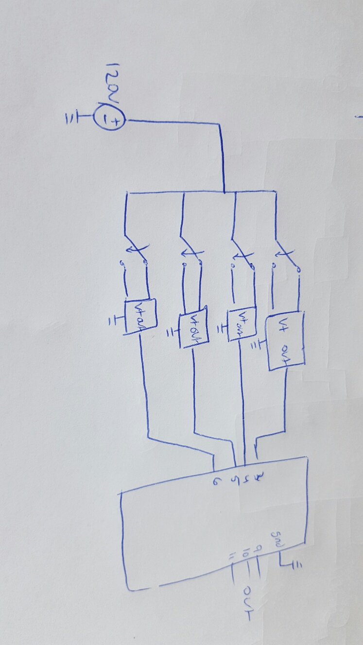
a schematic that i came up with for the inputs is attached as well
I said USB charger So it is a kind of wall wart itself.
If want to spend the money on the switches, be my guest. But it's not efficient in my book And if you already spend 200 bucks+ another 30 on chargers doesn't hurt.
And how to wire them into mains is up to you. But a safe approach would be to switch a mains socket with the switch and plug the charger into that socket.
Next, you connect the GND of each charger to Arduino GND. And from each charger 5V you go to an Arduino pin via (so in series) with a resistor of at least 100k.
Using the 3-way nature of the switch is useless. Like I said, just see each state change (so the change from off to on or from on to off) as a single push of the button.
Al tough you could use the 3-way nature to add another switch (but that does the same) at another location. Just use the 3 way switch as you're used to in normal applications but let it switch a usb charger. That way you have multiple (mains) switches that input as one to the Arduino. And it does not matter it thats a touch switch or not.
ok so the code works wonderfully with buttons, however when i switch over to the AC switches i get a flickering of the lights cycling through RGB and off as if the switches are being pressed due to the alternating of the current. i have 130k ohm resistors wired to be "pull up" im using USB chargers and USB wires as septillion said, but my lights are still flickering. just wondering how to fix this issue? i have tried a higher resistance as well, may need MUCH higher resistance?
This is the moment you post a full circuit diagram of the setup
For example, I never talked about a pull up, only about a series resistor.
And, like I said, the touch switches do one press = on, second press = off, third = on etc. It toggles while a normal button is only on as long as you press it. Because the input is different you need different code Now you need to detect a state change. Every change from on to off, or from off to on is a single button press. Now when you detect that you do the same as what you now do when a button is pressed.
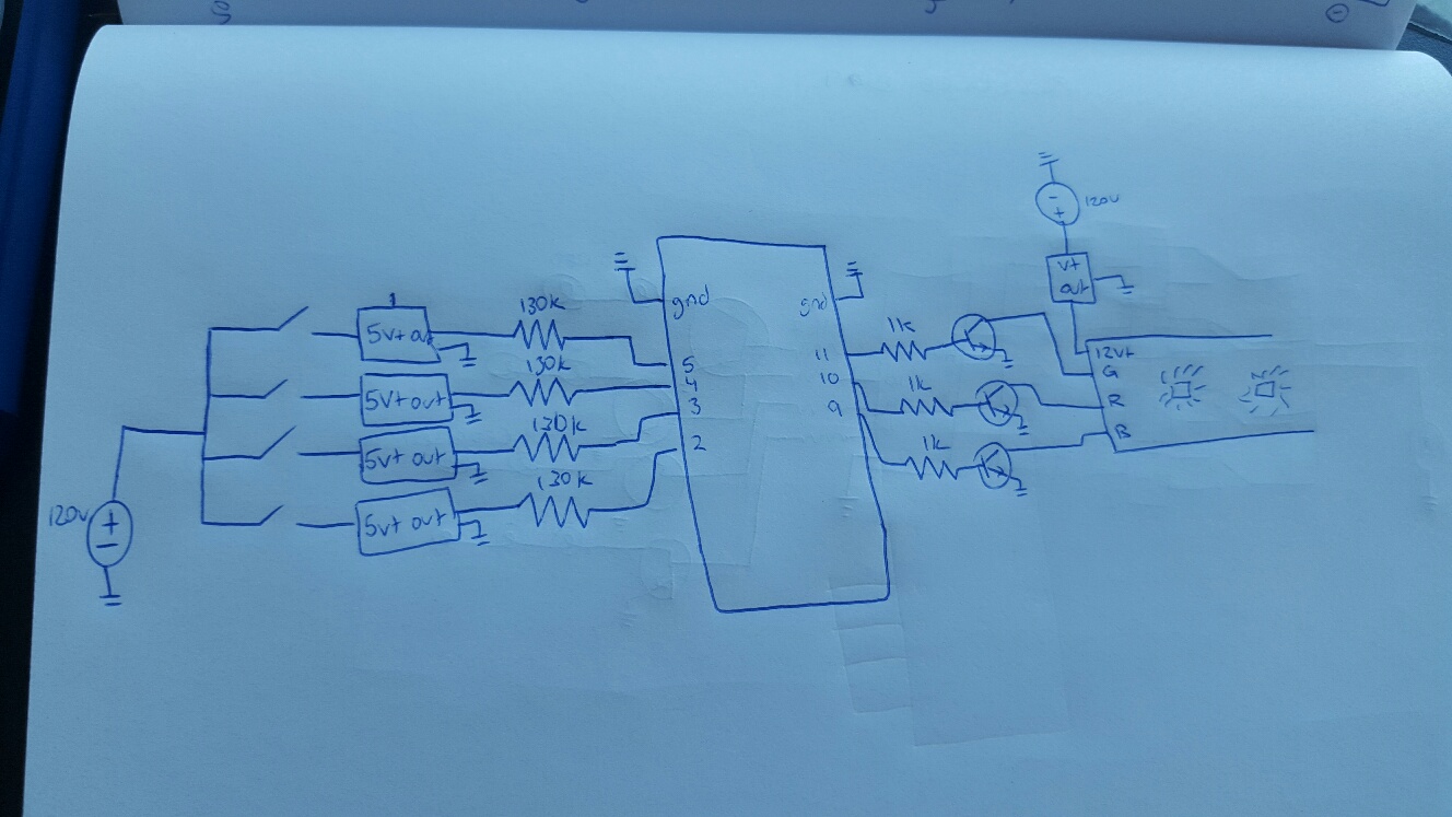
so below i attached what i have now, put the resistors back in series.. also attached my code based on putting together many other things from this forum that i had found on debouncing and state changes. on a side note my Arduino is now not being read by my computer either... this is a pain in the a$# project .. lol one thing leads to another.
The circuit looks kind of okay. But what powers the Arduino? (Nothing is connected to it )
And I hope you just made a drawing error and the other side of the mains (120V Neutral) isn't connected to GND... And I think the USB chargers have a Neutral connection as well. Mains and low voltage for the Arduino and leds should be completely separate. Can you confirm this is a drawing error and redraw the circuit?
Then off to the code. First thing I notice you try to do a debounce. Aside from the code for that isn't right I don't think you'll need it. The chargers are "slow" devices and I don't think they have bounce (but in a worst case they might).
Then I see a weird piece of code for the state change
                if (red_switchState == HIGH){
                    mode=1;
                }
                else {
                    mode=1;
                }
And if you start using arrays reading all the switches is as simple as
void checkSwitches(){
  for(byte i = 0; i < 4){
    if(digitalRead(switchPins[i]) != lastSwitchStates[i]){
      mode = i;
    }
  }
}
But the main problem is the wrong debouncing.
Ow, and a small tip. Try to use one time of naming conversion. So always use thisAsVariable or this_as_variable (with most C programmers favoring the first). Mixing them is only confusing. But great job not making the beginners mistake by using short but non-explaining names
Same for the position of a bracket. Or always behind a condition
if(this){
  //code
}
or always on a new line
if(this)
{
  //code
}
Just to make the code more consistent and clear.
And press ctrl+t for fun. The code indentation is a bit extreme.
Yea the schematic was just a quick sketch those grounds are a quick mental note saying they connect at the same node to the mains neutral, my fault. The Arduino will be powered by a 9VDC adapter but most of the time it is running the code while plugged into my computer so i can make quick edits to code, and obviously unplug if i need to make changes to circuitry.
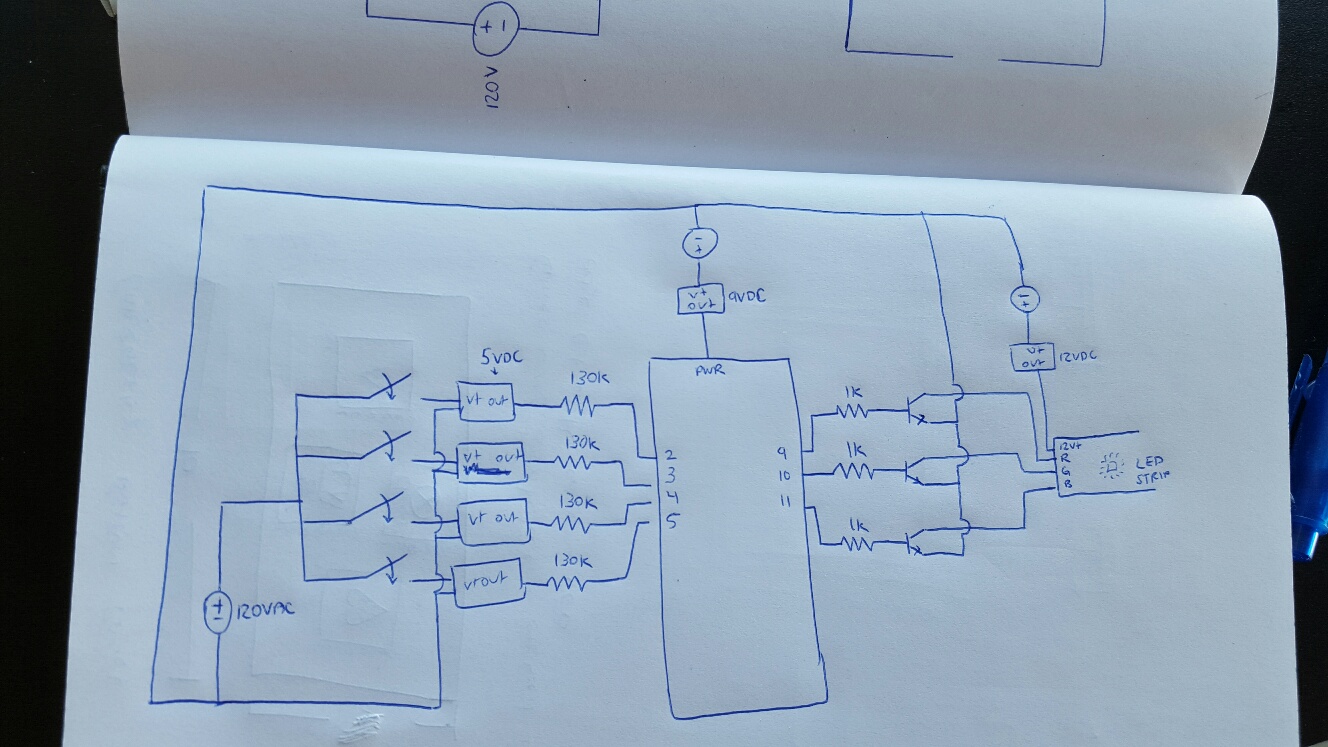
to be more accurate i have another schematic that is attached and this is exactly how my circuit is hooked up currently.
this is more help than i have ever received in my university programming or circuits class,
thanks.
RyansProjects:
to be more accurate i have another schematic that is attached and this is exactly how my circuit is hooked up currently.
Close but no... Because now non of the low voltage parts have a GND, the 9V and 12V adapter don't have a neutral and where did you get the multiple 120V sources from? I know it's nitpicking but how often we come across a problem where the problem is in the details. Also, making good documentation is a joy when you start to work on this in a couple of months etc. So give it one more try
But I think (but don't know for sure) the connection part is alright. But like I said, the debounce part is just wrong and you can probably just leave it out because I don't expect an USB charger to bounce.
Hi,
I know this Thread is old, but it is exactly my project
I use an Arduino/Genuino Micro an 3 MOSFETs to power an LED Strip. 5V at the moment so I don't kill the board.
The Idea is that when no Input is present it should be Blue and depending on the A1-A4 Input, change to a set color.
I used most of the Code from RyansPrjects to make the switch between the color and some I found online (Ultimate Guide to Connecting LED Light Strips to Arduino) so please don't be mad.
It is almost fine, but I have the problem that the colors don't really change the way I want them to
change.
The wiring for the LED Strip is from the MakeUseOf Homepage.
The Inputs on A1 to A4 seem to give back random values.
I used the internal pull-up and pull the Input down to GND with a switch.
Can you help me to find what I did wrong?