After having experimented with all manner of displaying digits on a 7 Seg display and eventually realising that none of them were actually multiplexed, I have cobbled together a few codes written by other people. I had seen some demonstrations where people had started the multiplexing with a noticeable delay between individual segment displays and then progressively reducing the delay until it was inperceivable and thus displaying a steady digit. I have altered the delay function so now it decreases to a certain point but then goes back to the initial delay period. I can see why it does this but I cannot work out how to get the delay period short enough to allow for the steady digit display I am aiming for. Can anyone please offer me a gentle nudge in the required direction ![]()
Thanks Pedro
// 7-Segment LED counter, multiplexing using 74HC595 8-bit shift register.
// Code mangled together from these sources - thanks fellas
// http://www.sweeting.org/mark/blog/2011/11/27/arduino-74hc595-shift-register-and-a-7-segment-led-display
// http://thecustomgeek.com/2011/06/29/multiplexing-for-a-7-year-old/
// http://nootropicdesign.com/projectlab/2009/10/25/led-clock/
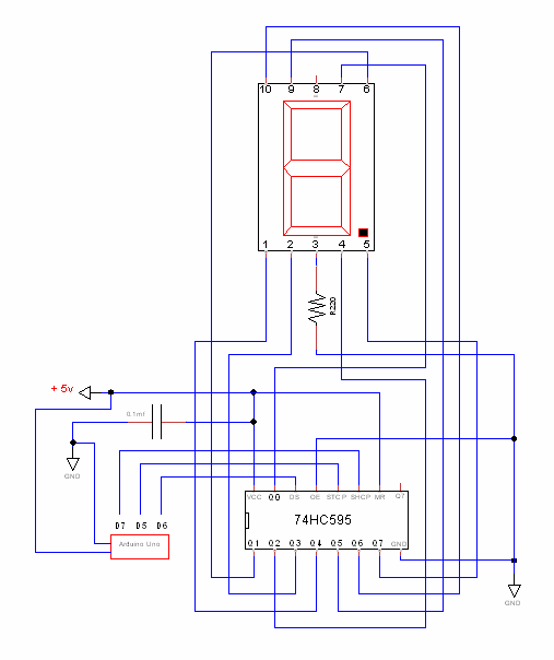
const int latchPin = 5; //Pin connected to Pin 12 of 74HC595 (Latch)
const int dataPin = 6; //Pin connected to Pin 14 of 74HC595 (Data)
const int clockPin = 7; //Pin connected to Pin 11 of 74HC595 (Clock)
int timer = 500;
const byte number = B11111110; // Describe each digit in terms of display segments
void setup()
{
pinMode(latchPin, OUTPUT); //set pins to output
pinMode(clockPin, OUTPUT);
pinMode(dataPin, OUTPUT);
}
void loop()
{
Serial.println(timer);
show(number);
}
void show( byte number)
{
/* Loop over each segment in the "number" we're about to display,
* and illuminate only one segment at a time.
*/
for(int j=0; j<=7; j++)
{
byte toWrite = number & (0b10000000 >> j);
if(!toWrite) // If all bits are 0 then no point writing it to the shift register,so break out and move on to next segment.
{
continue;
}
shiftIt(toWrite); // Otherwise shift it into the register
}
}
void shiftIt (byte data)
{
digitalWrite(latchPin, LOW); // Set latchPin LOW while and clock these 8 bits in to the register to illuminate a single segment.
for (int k=0; k<=7; k++)
{
digitalWrite(clockPin, LOW); // clockPin LOW prior to sending bit
/* Do another bitwise AND against a mask to check the state of
* each bit as we clock it in.
* Note that in our case, we need to set pinState to 1 (HIGH) for
* "On" as the 74HC595 is sourcing current when using a common cathode display
*/
if ( data & (1 << k) )
{
digitalWrite(dataPin, HIGH); // turn "On"
}
else
{
digitalWrite(dataPin, LOW); // turn "Off"
}
digitalWrite(clockPin, HIGH); // and clock the bit in
}
digitalWrite(clockPin, LOW); //stop shifting out data
digitalWrite(latchPin, HIGH); //set latchPin to high to lock and send data
// put delay here if you want to see the multiplexing in action!
delay (timer = (timer - 10));
if(timer <=1)
timer = 500 ;
}