I'm working on my first arduino project for work where I am trying to build a temperature probe with each thermistor read and saved with an arduino. I'm a biologist so my electric engineering knowledge is very limited but very happy to learn.
For now, I would like to use 8 thermistors with only one reference resistor (they are too expensive to buy one for each thermistor). I have the 4067 multiplexer but I am struggling to figure out how to connect everything so it does what I want it to do.
I've attached a picture of how I've wired everything. I'm not sure how the current flows through the multiplexer and would greatly appreciate some help with this.
My logic behind connecting it the way I did was:
Current starts at 3.3V goes through thermistor C9 (selected in code) through multiplexer to Sig which is connected to the resistor and A0, hopefully creating a voltage divider. Resistor is connected to ground on multiplexer.
Multiplexer gets power from the 5V arduino pin. Does that work? Or should that also be the 3.3V?
I'd also like to add a SD and RTC module but they all us the same pins like the multiplexer. Is there a way to do this? Can I use the same pins for multiple modules?
The 4067 is not an ideal switch, but has a resistance around 60ohm (It varies a bit) that will be added to the thermistors resistance, reducing you precision. How much depends on the resistance range of you thermistors.
The ADC on a Arduino is not very precise with only 10 bits.
You precision will also be depend of how stable the 3.3V output is compared to the 5V or the internal Arduino reference.
If you need such expensive resistor it is probably you want it very precise. I think this will not work!
The 4067 have some ON resistance - about 200 Ohm IIRC. The resistance changes slightly with applied voltage, supply voltage, temperature...
Arduino's ADC is not precise enough. If you need anything better than 1% resistor you need better ADC.
Possible fix is taking 1% resistor and calibrating the whole thing?
Also you don't need a multiplexer for this. Connect thermistor to Arduino's pins. Turn one as OUTPUT HIGH and other as INPUT and it will be as if it the one were connected to 5V and the others disconnected.
Why you want to connect them to 3V3? Connecting them to 5V makes the output of the voltage divider proportional to 5V. Since output of the Arduino's ADC is also proportional to 5V by default (in 5V system) this makes the reading independent on the supply voltage (in theory).
Which Arduino, and why the 3.3volt thermistor supply.
A thermistor/resistor pair is ratiometric, and must be powered from the same VCC (Vref) as the Arduino.
Powering the thermistor/resistors from a different supply defeats ratiometric compensation, and results in a less stable supply dependent readout.
$0.10 1% metalfilm resistors are perfectly ok for for thermistors. Calibration of that resistor/thermistor pair can must be done in software anyway.
If you switch thermistor/resistor pairs with a 74HC4067, then 4067 switch resistance is not important.
If you switch thermistors to one resistor, there will be dragons.
Leo..
Why not use ds18b20? More accurate than thermistor+Arduino ADC, multiplexing not needed. Many sensors can be attached to a single wire & read independently.
HKJ-lygte:
The 4067 is not an ideal switch, but has a resistance around 60ohm (It varies a bit)
No ...
Smajdalf:
The 4067 have some ON resistance - about 200 Ohm IIRC.
Correct. It depends you see, the 4067 is in the order of 200 Ohms, the 74HC4067 is around 60 Ohms.
It certainly is nonsensical to be concerned about any sort of precision resistors and then consider using an analog multiplexer as part of the potential divider.
Paul__B:
Correct. It depends you see, the 4067 is in the order of 200 Ohms, the 74HC4067 is around 60 Ohms.
It certainly is nonsensical to be concerned about any sort of precision resistors and then consider using an analog multiplexer as part of the potential divider.
Can you even get the 4067 anymore?
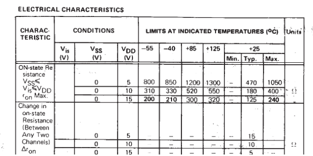
Anyway you are wrong about the on resistance for it, it can be well above 200ohm, here is from a old CD4067 datasheet:
"In the order of 200 Ohms," - yeah, well, 1k is in that order.
The only use for the non-HC version of the 4000 series is where you want to use odd voltages - like 12 V. And analog multiplexing is about the only place where you would.
These were recommended by a sea ice physics lab which they used for the same purpose that I will use them for.
I will use the thermistors to build a thermistor probe to use for ice core measurements. Temperatures will range from -10 to +10 deg C.
I have the HiLetgo CD74HC4067 CMOS 16 Channel 16 CH Digital Analog Multiplexer, which has more channels than I currently need but I wanted to be on the safe side as I might increase the number of thermistors.
Another group is using an Arduino for the same purpose and they gave me the tip of averaging several reads to account for noise.
Paul__B, are there any better options than a multiplexer?
Using a 0.01% resistor is completely mismatched to the rest of the parts.
To get high precision use two muxes, one for the sense and one for the resistor. Use a better ADC (ADS1115 modules is cheap and has good precision) and also measure on the resistor, this way you can calculate around the loss in the mux that is used to switch the resistor.
10k is the wrong value to measure melting ice with a 10k thermistor.
You should use about same value resistor as the thermistor when it is 0 degrees C, which is about 30k.
If you don't then you loose A/D resolution at that temp.
Utter nonsence to use a 0.01% resistor for a thermistor.
You must calibrate each individual thermistor anyway.
An easy way is to start off is to measure each resistor with a good DMM,
and use that (with 3 decimal places) in your code.
@ HKJ-lygte
An ADS1115 is the wrong type of A/D for a ratiometric thermistor/resistor.
You should use a ratiometric A/D for that.
And yes, the one-wire DS18B20 with it's 1/16 degree C resolution (not accuracy, which you must calibrate) might be easier to use.
Leo..
HKJ-lygte:
There is no need for that when you measure voltage for both reference resistor and sensor, this will eliminate and reference errors from the result.
Sure, if you don't mind the extra hardware, and code, and calibration.
Leo..
Wawa:
Sure, if you don't mind the extra hardware, and code, and calibration.
Leo..
Calibration? You dont need any more calibration.
The extra hardware means a resolution of at least 10000 count from 0.1V to 5V on the ADC.
Not much coded needed, there a lots of libraries for the ADC, I have done one where you can use all the capabilities of it.
Did you consider using a platinum RTD and MAX31865. It may be a bit more complicated and expensive but you should get much better stability and precision.