ShermanP:
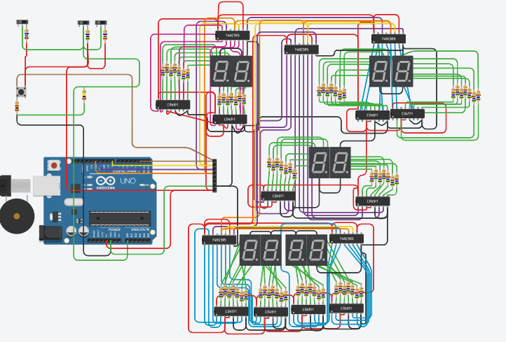
It's an interesting question. If I understand correctly, you are using 14 individual digits driven by 21 chips. I would hate to have to breadboard that. But yes, with any form of multiplexing, the flicker problem arises. We watch TV at 30 fps, and most movies are still 24 fps, but for reasons I don't really understand the common target refresh rate for digitial displays is 60 Hz to guarantee there will be no flicker or even shimmer. That means if you are turning on one digit at a time, that digit is on only 1/14 of the time, so the overall refresh rate will have to be 840 times per second, or essentially once per milli, to give an individual digit a 60 Hz refresh rate. There is a chance that will conflict with other functions, but on the other hand the actual time to do a refresh is usually very short - on the order of tens of microseconds.
A microprocessor can usually handle multiplexing a couple of digits, or even four, with no problem, but at some point on the way to 14 digits it starts to make more sense to transfer the display operation to another chip(s) which devotes its full time to the displays, and actually you have done that in a way with your 21 chips. The MAX7219 that Paul__B referred to is another solution, and I believe it handles 8 digits, so you would need two of them, which is a lot better than 21. And as he says, they would do the multiplexing for you.
But on the chance that there might be an intermediate solution, could you tell me how many pins you could reasonably devote to the display function, how much current one of your displays draws when displaying "8" brightly enough to suit you, and whether you need to use any of the decimal points? Also, have you already bought all this stuff?
Some of the stuff i have already bought, some I have on its way along with my arduinos.
This project started as a repair job on an old bubble hockey game, where i was working on replacing all of the ICS (at some point i decided that chasing the problems in the original board would be far more time consuming than just replacing everything since it had been repaired at least a half dozen times since the 80s.
once i did that, and found that the original ROM was damaged, and unable to be fully read, with no hope of finding the original to rewrite it, i decided to start from scratch with arduino.
I started by duplicating the original scoreboard in tinkercad to be able to test my code with it, with the intent on reusing it. which then as things do, turned into a case of "If im rewriteing the whole thing, why not make it do MORE than the original?"
and so as it were, the scoreboard grew from 6 individual digits (scores and period), to the current 14. (double sided, so in actuality, 28 total)
i plan to reuse the existing harness that runs from the control board to the top of the scoreboard, it carries 12v for the lights, 5v for the scoreboard, both from the main power supply, a ground, and 4 pins for communication with the scoreboard.
I have started looking at the MAX ICs the last day or two when i discovered that newer versions of the game actually use the MAX chips on their scoreboards. Im still not too far in to change things, and im sure the MAX code would likely be similar to what i have with minimal changes.
im not a total stranger to electronics, and coding, was a software developer in another life, and been repairing my own circuitry since i was a teen. just never really stopped to fully understand what the ICs did until the last year or so, so its been a fun learning experience.
thanks for your comment which actually helped to answer my original question without proposing 4 digit displays that arent suited for this particular project. the refresh is what i was concerned most about, as there are points where triggers are activated which interrupt the code, and wait for a second trigger to be active before resuming, in such a case where for example, maybe to goal sensor was activated, but the puck jammed and didn't make it to the center ice sensor allowing the resume, the scoreboard refresh would be interrupted.
So based on your answer, my best option would appear to be using the MAX chip, and saving that, stay with my existing setup.