Hey guys and gals, i made a script for my digispark with adafruit but i ran into some issues.
First let me explain the setup, i uploaded script on DigiSpark and ițm sending from my android via bluetooth comands to change colors and swap between effects, the comands are a string composed of an x number of characters.
The first function grabs the strin, the string is parsed and then values are stored.
The second function in the loop is checking for the values and then calls on adafruit to start the LEDs.
Now the problem is that while the second function runs, it kind of gets stucked on doing that, run the leds, doing math on colors and all that and i had to do some really ugly coding to make it work, and even then it works mostly because of an buffer overflow issue, the chip kind of freezes for a while and itțs able to get the new values.
I have to call the first function time and time and time again and overall itțs a mess even if it works.
Digging around i realized that it's mostly a multi tasking issue. Or better said, lack of...
I very new to all this, i managed to scrap the net for codes, put the program togheter made an android app etc, learned quite a bit in the last week but i'm not even noob status. lol.
Now what i need is to have function a () to check constantly for bluetooth comunication/serial and when it gets info to stop function b () and restart it so it can grab the new values and do it's thing.
If you are using a DUE then uMT is a great multi tasker.
If you are using the ESP8266 OS version or a ESP32, then the OS, called freeRTOS, is the route to go for multi-tasking, and if using an ESP32 you can use multi-processing, along with multi-tasking.
You can write tasks without an OS on plain Arduinos. You can make the time slices Very Small by cutting long jobs into steps run by a finite state machine (the name sounds bigger than the technique) and thereby make OS-run PC's look jerky as to tasking.
This sticky thread (stays up near the top) can get you started: Demonstration code for several things at the same time.
These are some of Nick Gammon's tutorials, all well done.
Serial communication in combination with Neopixels is a tricky job. You basically can only send one character, you'll have to wait for a reply from the receiver that the character was received before sending the next character.
Reason is that while Neopixels are being updated, interrupts are disabled. So if you transmit too many characters while the strip is updated, part of them will be lost (because serial reception also relies on interrupts).
As you haven't posted your code, it's difficult to advice further. The above approach will require you to rewrite your cell phone application.
I have a Neopixel code that runs off PWM/Interrupt and allows you to receive and process as many serial characters (using interrupts) as you want.
Not familiar on the DUE but I supposed it's just a matter of PWM initialization. I don't have fancy library though for building nice pattern or animation.
hzrnbgy:
I have a Neopixel code that runs off PWM/Interrupt and allows you to receive and process as many serial characters (using interrupts) as you want.
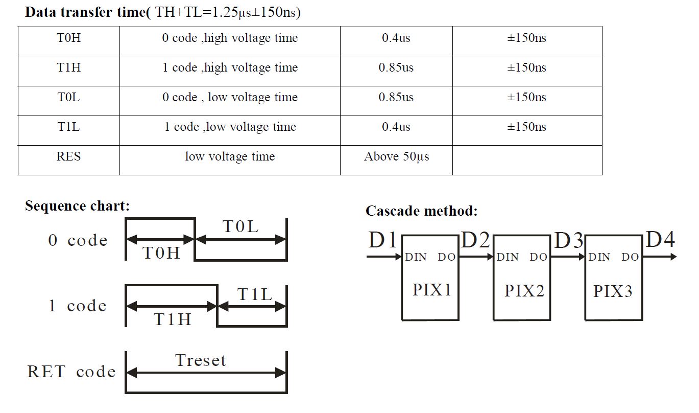
The basic idea is use a PWM with a period of 1.25 usec (what the Neopixel requires per bit of data)
The duty cycle of the PWM signal is then modified to represent a "high" bit (or 0.85 usec) or a "low" bit (or 0.4 usec)
The magic happens on the overflow interrupt of each PWM pulse. This is where you change the duty cycle of the next pulse (to represent the next bit to send to Neopixel)
The following timer overflow ISR is for SAMD21 but can be adapted to just about any uC
void TC5_Handler(void)
{
	if(REG_TC5_INTFLAG & TC_INTFLAG_OVF)
	{
		// reset interrupt flag register
		REG_TC5_INTFLAG = TC_INTFLAG_OVF | TC_INTFLAG_MC0 | TC_INTFLAG_MC1;

		/*******************************************
		set PWM setting for the next cycle
		*******************************************/

		// generate a period of 1.25 microseconds
		REG_TC5_COUNT16_CC0 = 59;

		// set the duty cycle for the next cycle based on NeoPixel data, 0.4 usec for low, 0.85 usec for high
		REG_TC5_COUNT16_CC1 = ((neopixelData[neoCnt01] & 0x80) ? 39 : 19);

		// update variables
		neopixelData[neoCnt01] = neopixelData[neoCnt01] << 1;
		neoCnt02++;

		if(neoCnt02 > 7) {
			neoCnt02 = 0;
			neoCnt01++;
		}

		tc5BitCounter++;

		if(tc5BitCounter < 769)
		{
			// let it rip
			REG_TC5_CTRLBSET = TC_CTRLBSET_CMD_RETRIGGER;
			while(REG_TC5_STATUS & (TC_STATUS_SYNCBUSY));
		}
		else
		{
			// this section effectively stops the update by not re-triggering timer 5
			tc5BitCounter = 0;
			neoCnt01 = 0;
			neoCnt02 = 0;
		}
	}
}
As you can see, neopixelData array contains the 96 bytes (32 neopixels at 3 bytes each), and each interrupt, a bit is shifted, until the LSB, where a byte counter is incremented to point to the next byte in the array. That's what the neoCnt01 and neoCnt02 are for. The tc5BitCounter is the total number of bits to send (96 bytes x 8 ), and stops the timer re-triggering.
I think a minimum of 16 MHz clock is needed to generate resolution needed for the duty cycle counter register. Other than that, it should be fairly standard PWM initialization. Also, must keep the ISR below 50 usec or the Neopixel resets. And it also helps if your uC have interrupt priorities so you can assign PWM the highest and it won't be pre-empted by another interrupt.
The PWM init follows
void neopixelTimerInit(void)
{
	// enable power manager for timer5
	REG_PM_APBCMASK |= PM_APBCMASK_TC5;

	// enable alternate pin function on PB11 for TC5 waveform output
	REG_PORT_DIRSET1 = PORT_PB11;
	REG_PORT_OUTCLR1 = PORT_PB11;
	PORT->Group[1].PMUX[5].reg = PORT_PMUX_PMUXO_E;
	PORT->Group[1].PINCFG[11].reg = PORT_PINCFG_PMUXEN | PORT_PINCFG_DRVSTR;

	// reset TC5 registers
	REG_TC5_CTRLA = TC_CTRLA_SWRST;
	while(REG_TC5_STATUS & (TC_STATUS_SYNCBUSY));

	// run TC5 at 48 MHz (48MHz DIV1)
	REG_TC5_CTRLA = TC_CTRLA_PRESCALER_DIV1 | TC_CTRLA_WAVEGEN_MPWM | TC_CTRLA_MODE_COUNT16;

	// enable one-shot operation for timer 5
	REG_TC5_CTRLBSET = TC_CTRLBSET_ONESHOT;

	// enable overflow interrupts only
	REG_TC5_INTENSET = TC_INTENSET_OVF;

	// set initial top counter values
	REG_TC5_COUNT16_CC0 = 0xEFFF;

	// set initial match compare value
	REG_TC5_COUNT16_CC1 = 0x0FFF;

	// enable timers 5 to activate values
	REG_TC5_CTRLA |= TC_CTRLA_ENABLE;
	while(REG_TC5_STATUS & (TC_STATUS_SYNCBUSY));

	asm("NOP");
	asm("NOP");

	// stop timer for now
	REG_TC5_CTRLBSET = TC_CTRLBSET_CMD_STOP;
	while(REG_TC5_STATUS & (TC_STATUS_SYNCBUSY));

	// enable high priority TIMER 5 interrupt
	NVIC_SetPriority(TC5_IRQn, 1);
	NVIC_EnableIRQ(TC5_IRQn);

	return;
}
IIRC there is a tolerance on Neopixel signal timing, a little margin to be within.
1.25 usecs is 18 cycles. It takes 1 cycle to toggle a pin by writing a 1 to the matching PINx register bit.
How time-wide can a single Neopixel bit be?
edit: found it,
Principle of operation
The WS2811 expects two things:
A pulse (i.e., rectangular) wave signal with a frequency around 800KHz—other frequencies work as well, but we'll stick to 800KHz in this tutorial—that sets the intensity values in an internal shift register. Let's note however, that the WS2811 behaves differently than a standard shift register in that the data are shifted in a First-In Last-Out fashion.
After the data are shifted into place, the WS2811 expects a low signal lasting at least 50μs in order to latch the data to their respective outputs.
Yes, there of all places.
Shift bits and as long as you do the next one before 50us (easily done) you should be good.
I don't need timers or a port, just a digital pin.
It's a rabbit hole. Not only do some of the LED datasheets flat out lie about timings, but there are a lot of NeoPixel variants and it's usually hard to know exactly what parts they've put on a strip. I wrote some PIC code to drive Neo's and it worked really well with SK6812's but not WS2812B's. For example, it is claimed that the RES time is 50us. (see chart above). But I found experimentally that it is much shorter. I guess what has happened is that the parts have been manufactured differently than the data sheet indicates.
The Adafruit code uses some really cute assembly code to ensure that the branches that are necessary to loop through the source buffer, are "hidden" in bit intervals, and also magically symmetrical regards a branch taken or not taken.
Any processor that has significantly faster instruction execution has a huge advantage, since as evidenced above, it then becomes possible to convert the bit-banging to a timer exercise.