Hi! I recently started my Arduino journey with a kit I bought online and some YouTube tutorials. This is my first project that I am attempting on my own and I got 90% of my hardware doing what it is supposed to. I am struggling with the code to get the last bit working the way I want it to. My project consists of 2 x LEDs, 1 pushbutton, 1 x buzzer, 1 x photo resistor and some 330/10K resistors (I will include a picture of my setup and code with this post). The ultimate aim of my project is to create an alarm to inform me when we have a power outage (we have regular power outages and have solar installed, but need to manage our power consumption carefully when there is a power outage). The way I want to achieve this is to read the light level of an indicator light installed on the distribution board (DB) that receives the main electrical supply. I got my project to work to the point where my generic UNO is reading the light values from a photoresistor and then turning on a green LED when it reads a value above the set threshold, or turning a red LED + the buzzer on when the light value falls below the set threshold. If I push a button, it mutes the buzzer for about 20 - 30 seconds. This is where I need help. If the buzzer goes off, I want to be able to mute the buzzer (by pushing the button) and the buzzer should stay muted until the next occasion that there is a power outage. I couldn't come up with a suitable solution to mute the buzzer as I wanted and tried a 24-hour delay in the code after the button was pushed. But as stated before, the result I am getting is a delay of +- 20-30 seconds instead of the intended 24 hours. The delay solution is also not helpful as it stops the code from continuing to read the light levels whilst the delay is still active. Could someone please assist with a solution to fix my code, or point me in the right direction? Your assistance will be greatly appreciated.
My code and a Tinkercad image of my hardware is included below.
const int photoresistorPin = A0;
const int greenLedPin = 5;
const int redLedPin = 3;
const int buzzerPin = 4;
const int switchPin = 2;


int buttonValue;
const int dt = 100;
const int dt2 = 86400000;
int lightValue;
bool buzzerEnabled = false;

void setup() {

  pinMode(greenLedPin, OUTPUT);
  pinMode(redLedPin, OUTPUT);
  pinMode(buzzerPin, OUTPUT);
  pinMode(switchPin, INPUT_PULLUP);  // Use internal pull-up resistor

  Serial.begin(9600);
}

void loop() {

  lightValue = analogRead(photoresistorPin);
  buttonValue = digitalRead(switchPin);


  Serial.println(lightValue);
  Serial.println(buttonValue);  // Print light value to serial monitor


  if (lightValue > 800) {
    // Light is bright
    digitalWrite(greenLedPin, HIGH);
    digitalWrite(redLedPin, LOW);
    noTone(buzzerPin);
    buzzerEnabled = false;
  }

  if (lightValue < 800) {

    // Light is dim
    digitalWrite(greenLedPin, LOW);
    digitalWrite(redLedPin, HIGH);
    buzzerEnabled = true;
  }

  if (buzzerEnabled) {
    tone(buzzerPin, 4000);
  }

  if (buzzerEnabled && buttonValue == LOW) {
    noTone(buzzerPin);
    delay(dt2);
  }

  delay(dt);
}
your requirements should easily translate into a state diagram and then into code.
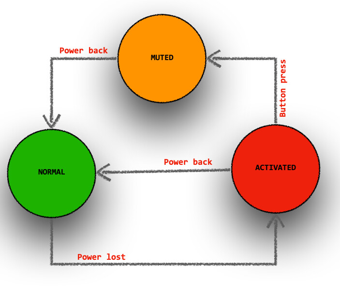
As you describe your needs, I can identify 3 states NORMAL, ACTIVATED, MUTED
NORMAL is when power is working fine
ACTIVATED is when you lost power and the alarm is sounding
MUTED is when you lost power and the alarm has been shut off.
in NORMAL mode, you go to ACTIVATED if power is lost
in ACTIVATED mode, upon button press you go to MUTED and if power comes back you go to NORMAL
in MUTED mode if power comes back you go to NORMAL
Yes, a state machine looks like an excellent way forward.
The key trick in a state machine is instead of trying to build the logic of the program from the right set of external inputs (buttons, and sensors and timers, etc...) and increasingly complicated if statements, you add an additional "state" variable for what the system should be doing, and use that variable to simplify the logic. At the highest level, your system sounds like it is supposed to be either ARMED, BUZZING, or MUTED (other words for @J-M-L's NORMAL, ACTIVATED and MUTED), and if you had a variable that tracked that, it would simplify the logic.
Here's @J-M-L's sketch with a few tweaks realized (!) in simulation:
The code:
// https://wokwi.com/projects/419523916199154689

const byte switchPin   = 2;
const byte redLedPin   = 3;
const byte buzzerPin   = 4;
const byte greenLedPin = 5;

const byte powerPin = 6;

const byte photoresistorPin = A0;
const int photoresistorThreshold = 777;

enum : byte {NORMAL, ACTIVATED, MUTED} state = NORMAL;

bool powerIsOff()
{
  bool power = analogRead(photoresistorPin) < photoresistorThreshold;
  digitalWrite(powerPin, !power);

  return power;
}

bool powerIsOn()
{
  bool power = powerIsOff();
  digitalWrite(powerPin, !power);

  return !power;
}

bool buttonIsPressed() {
  return digitalRead(switchPin) == LOW;
}

void alarmOn() {
  digitalWrite(greenLedPin, LOW);
  digitalWrite(redLedPin, HIGH);
  tone(buzzerPin, 777);  // 4000 = upset cat!
  state = ACTIVATED;
}

void alarmOff() {
  digitalWrite(greenLedPin, HIGH);
  digitalWrite(redLedPin, LOW);
  noTone(buzzerPin);
  state = NORMAL;
}

void buzzerOff() {
  noTone(buzzerPin);
  state = MUTED;
}

void setup() {
  pinMode(greenLedPin, OUTPUT);
  pinMode(redLedPin, OUTPUT);
  pinMode(buzzerPin, OUTPUT);
  pinMode(switchPin, INPUT_PULLUP);
  alarmOff();
  powerIsOff();  // just to set the power LED correctly at startup
}

void loop() {

  switch (state) {
    case NORMAL:
      if (powerIsOff()) alarmOn() ;
      break;

    case ACTIVATED:
      if (powerIsOn()) alarmOff();
      else if (buttonIsPressed()) buzzerOff() ;
      break;

    case MUTED:
      if (powerIsOn()) alarmOff();
      break;
  }
}
There were no typos in @J-M-L's original sketch. I left the state names, I didn't think one set was better than another, and both are vaguely unsatisfactory but I have never been any good at naming things, so.
I would move the changes to the state variable into the state machine FSM switch and possibly make it a local variable. This keeps the FSM logic contained.
There are 2 hard problems in computer science: cache invalidation, naming things, and off-by-1 errors. -- Leon Bambrick
My personal rule for naming states is to describe what the FSM is "doing", as if I were pointing at a black box and trying to describe the different things it does. I'm not defending my names, I just took words from the OP's title while I was replying.
The other trick in state machines is identifying the transitions between states, and the state diagrams are excellent for that. For example, you put your finger on SILENCED and ask yourself how you want to get back to MONITORING, and then draw and arrow and label it, and later write an if-statement do the transition. In #1, @edb_sa described a time limit, so you'd perhaps need to record the time you transitioned into SILENCED, and then check whether the elapsed time is long enough to transition out to MONITORING.
Indeed - and one thing I like with state machines architecture is that the code is usually easy to extend if we come up with another idea like adding a time based event. if you do it right, it does not lead to spaghetti code.
Yes. You could easily have arrows/transitions for both the "until a value is reached again" and "a 24 hour delay" event and then they each end up as separate, simple if-statements in the case SILENCED: state
I tested your amended version of @J-M-L solution and it worked perfectly! Thank you very much @J-M-L and @alto777 for your assistance to help me solve my query.