Hi everyone!
New to this world of Arduino and to the forum.
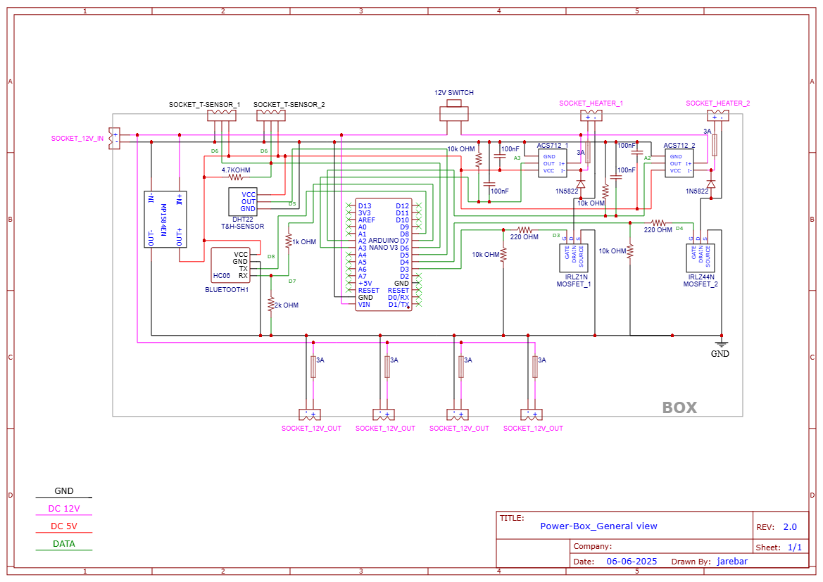
Decided to build my first project in the benefit of one of my hobbies: astrophotography.
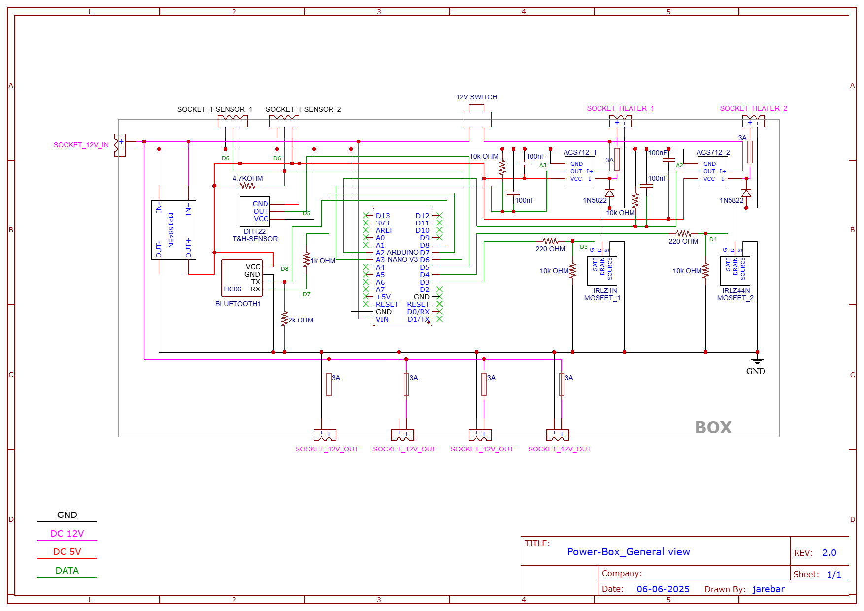
The project is a power-box to feed all the equipment and to control 2 dew heating stripes. Temperature and humidity sensors, bluetooth...
Since this is my first contact with this world, I wonder if you experts would be so kind to take a look at the circuit diagram to see any flaw.
To develop it, I've been self-taught with support from IA. I tried to keep it as simple as possible.
All feedback is more than welcome.
Thanks in advance!
1 Like
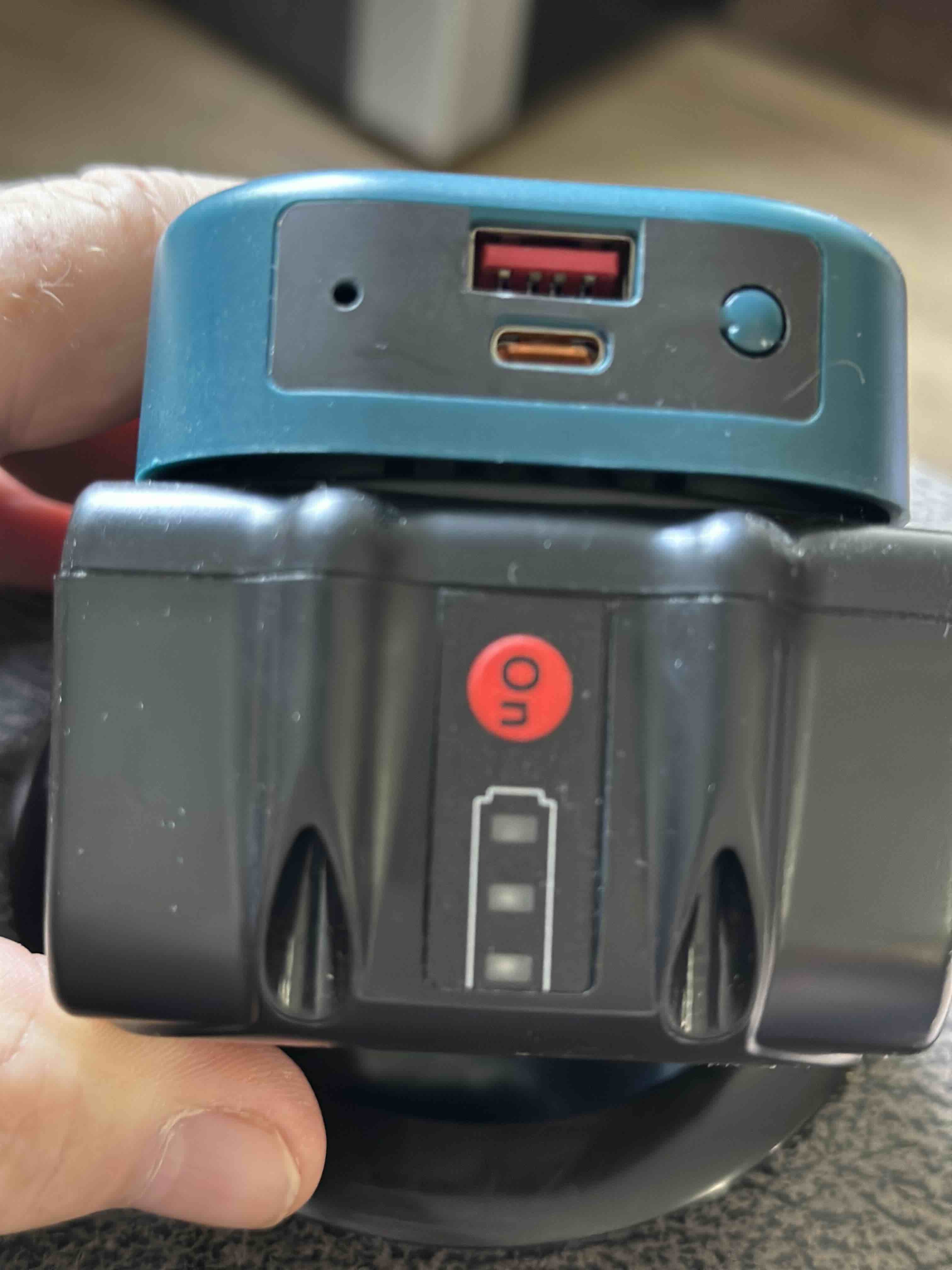
I am also an astro photographer and astronomer. I don't know what purpose an Arduino would have. My power for several heaters, tracker and camera power comes from 2 Makita tool batteries. I have several power packs as backup, just in case, but the Makitas are big enough.
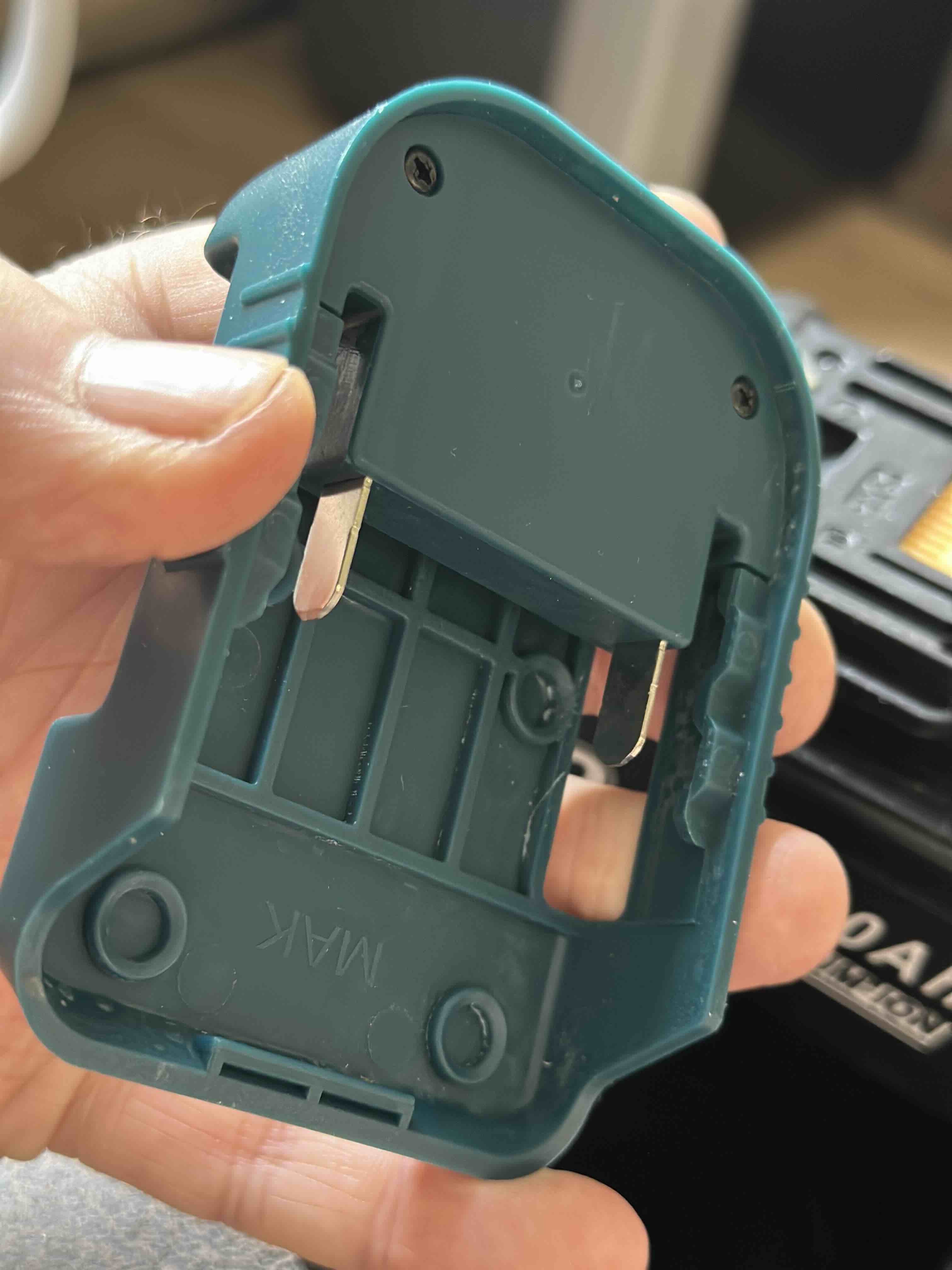
Would you care to share what battery box you are using or the hardware setup you designed to facilitate easy swapping out of tool batteries?
Connections on DHT22 are backwards.
True. Thank you!
No batteries. AC/CD converter. 12V - 5A. Just power splitter for camera, computer, mount and flats panel, and x2 dew heaters controlled by PWM from Arduino through MOSFET.
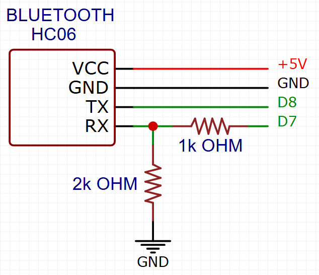
Recheck those resistor connections on the HC06 module!
What are these Tsensors?
Standard way of making use of portable power. If I needed 12V I would simply add a DC to DC converter commonly called Boost converter (5V to 12V)
1 Like
x2 DS18B20. One wire. Measure the temperature of the heating strips for the arduino to calculate the optimum temperature to avoid moist.
DHT is missing pullup.
Mosfet gate pulldowns should be on the left side of the gate resistor.
ACS output looks like you want to measure AC ..
Thank you @kmin
Copy pullup in DHT.
Pulldowns moved to the left.
Sorry but I don't understand your point regarding ACS output.
Does your module already have a pullup?
Could be. I'll check the data sheet.
Thanks! For some reason, I thought the battery box you run to the devices wouldn't have just positive and negative, but each of the single lithium ion cells broken out, thus risking unbalanced cells during device use and potentially damaging the batteries.
No, that is only needed when charging. Since the batteries are consumer devices the balance circuitry is internal. Can you imagine the typical (stereotype here) amurican properly connecting balance leads assuming of course he owned a proper charger?
BTW, that is true of any use case, the balance leads (typically a 2,3,4,5,6 pin JST connector) is only needed when charging. There are PCB circuit boards inside that do discharge protection.
All the mistakes you made would have been caught if you had double checked. I know that if you look at something too long you will just see what you want to see and not what is actually there.
You should take a break for a while then come back to the schematic and check it one more time.
1 Like
It was about your parallel RC filter.
But if you are using module, you shouldn't need anything.
Same thing with DHT, if you are using module, you shouldn't need additional pullup.
1 Like